
Related Manuals for Rae MiniRAE Plus PGM-76


Summary of Contents for Rae MiniRAE Plus PGM-76
- Page 1 MiniRAE Plus PROFESSIONAL PID OPERATION AND MAINTENANCE MANUAL (Document No: 002-4001) Rev. E RAE SYSTEMS INC. 680 West Maude Avenue, Suite #1 Sunnyvale, CA 94086 July 1998...
- Page 2 RAE Systems Inc. 680 West Maude Ave. #1 Tel: 408-481-4999 Sunnyvale , CA 94086 Fax: 408-481-4998...
- Page 3 11.7 eV lamps for one month. RAE's obligation under this warranty is limited to replacing or repairing, at RAE's option, any defective part if returned to a RAE authorized factory repair center, with shipping charges prepaid by the buyer, and which, upon inspection by RAE, shall prove to have been defective in normal use and service.
- Page 4 RAE's behalf any liability in any way connected with the sale of RAE products. THIS EXPRESS WARRANTY SHALL EXTEND TO BUYER OF RECORD ONLY AND NOT TO SALES MADE BY BUYER'S CUSTOMERS. EXCEPT FOR THE...
-
Page 5: Table Of Contents
MINIRAE PLUS OPERATION AND MAINTENANCE MANUAL ______________________________________________ Table of Contents 1.0 GENERAL INFORMATION ......1-1 1.1 General Specifications........ 1-2 2.0 OPERATION OF MINIRAE PLUS ....2-1 2.1 Physical Description........2-2 2.2 Two Mode of Operation......2-4 2.3 Keys and Display ........2-6 2.4 Power On/Off ........... - Page 6 MINIRAE PLUS OPERATION AND MAINTENANCE MANUAL ______________________________________________ 3.8 UV Attenuator Ring........3-14 4.0 PROGRAMMING IN HYGIENE MODE..4-1 4.1 Menu Options ........... 4-2 4.2 Keys for Programming Task ...... 4-4 4.3 Entering into Programming Task....4-5 4.4 Set STEL Alarm Limit ....... 4-7 4.5 Set TWA Alarm Limit........
- Page 7 MINIRAE PLUS OPERATION AND MAINTENANCE MANUAL ______________________________________________ 5.5 Select Calibration Data ......5-7 5.6 Calibration of MiniRAE Plus ...... 5-8 5.7 Set Sampling Period ........5-9 5.8 Clear Data..........5-10 5.9 Set Low Alarm Limit ......... 5-11 5.10 Set High Alarm Limit ......... 5-12 5.11 Set Hour and Minute .........
- Page 8 MINIRAE PLUS OPERATION AND MAINTENANCE MANUAL ______________________________________________ 7.0 THEORY OF OPERATION....... 7-1 8.0 MAINTENANCE..........8-1 8.1 Battery Charging and Replacement..... 8-2 8.2 Filter Replacement........8-5 8.3 Sensor Module Cleaning......8-6 8.4 Probe Assembly Cleaning......8-10 8.5 Lamp Cleaning and Replacement ....8-11 8.6 Pump Replacement........
- Page 9 MINIRAE PLUS OPERATION AND MAINTENANCE MANUAL ______________________________________________ DANS DES ATMOSPHERES CONTENANT DES NIVEAUX DE COMBUSTION DES GAZ.
- Page 10 MINIRAE PLUS OPERATION AND MAINTENANCE MANUAL ______________________________________________ ! WARNING ! -DO NOT PROCEED BEFORE READING- THIS MANUAL MUST BE CAREFULLY READ BY ALL INDIVIDUALS WHO HAVE OR WILL HAVE THE RESPONSIBILITY FOR USING, MAINTAINING, OR SERVICING THIS PRODUCT. The product will perform as designed only if it is used, maintained, and serviced in accordance with the manufacturer's instructions.
- Page 11 MINIRAE PLUS OPERATION AND MAINTENANCE MANUAL ______________________________________________ THE MODEL PGM-76 EQUIPMENT IS SUITABLE FOR USE IN CLASS I, DIVISION 2, GROUPS A,B,C,D OR NON-HAZARDOUS LOCATIONS ONLY. THE MODEL PGM-76IS EQUIPMENT IS CLASSIFIED AS TO INTRINSIC SAFETY FOR USE IN CLASS I, DIVISION 1, GROUPS A,B,C,D OR NON- HAZARDOUS LOCATIONS ONLY.
- Page 12 MINIRAE PLUS OPERATION AND MAINTENANCE MANUAL ______________________________________________ Special Note When the MiniRAE Plus (PGM-76) Professional PID is taken out from the transport case and turned on for the first time, there may be some residual organic vapor trapped inside the ionization chamber. The reading may therefore show a few ppm.
- Page 13 MINIRAE PLUS OPERATION AND MAINTENANCE MANUAL ______________________________________________ The battery switch also serves as a reset switch for the microprocessor inside the MiniRAE Plus Professional PID unit. If for some reasons, the unit is hang up ( for example, no response to key press or display funny characters on LCD display), turn off the switch and then turn it on again should reset the microprocessor.
-
Page 15: General Information
SECTION 1 GENERAL INFORMATION 1.0 GENERAL INFORMATION MiniRAE Plus is a Programmable Professional Photo- Ionization Detector (PID) to measure organic vapors in hazardous or industrial environments. It incorporates a sampling pump and data download capabilities for continuous toxic monitoring, site survey and leak detection applications. It can measure two classes of toxic gases: (1) organic vapors with the supplied 10.6 eV gas discharge lamp, and (2) chlorinated compounds with the interchangeable 11.7 eV lamp... -
Page 16: General Specifications
SECTION 1 GENERAL INFORMATION 1.1 General Specifications Table 1.1 Professional PID Unit Specification Size 7.1"L x 2.7"W x 1.8"H (18.0 cm x 6.9 cm x 4.6 cm ) Weight 18 oz with battery (0.510 kg) Detector Interchangeable 10.6eV or 11.7eV electrodeless ultraviolet discharge lamp with Teflon/stainless steel chamber... - Page 17 SECTION 1 GENERAL INFORMATION Accuracy +/- 2 ppm or +/- 10% of reading, calibrated to 100 ppm Isobutylene Response Time < 3 seconds to reach 90% of exposed concentration Key-pads 2 operation keys, 2 programming keys, and an ON/OFF key Alarm Setting Separate alarm limit settings for TWA, STEL, and Peak in Hygiene...
- Page 18 SECTION 1 GENERAL INFORMATION This page is intentionally left blank 1 - 4...
-
Page 19: Operation Of Minirae Plus
SECTION 2 OPERATION OF MINIRAE PLUS 2.0 OPERATION OF MINIRAE PLUS The MiniRAE Plus Professional PID Unit is a portable organic vapor monitor/sampler. It gives the real time measurements and activates alarm signals whenever the exposure exceeds preset limits. Prior to factory shipment the MiniRAE Plus is preset with default alarm limits and the sensor is pre-calibrated with 100 ppm Isobutylene gas. -
Page 20: Physical Description
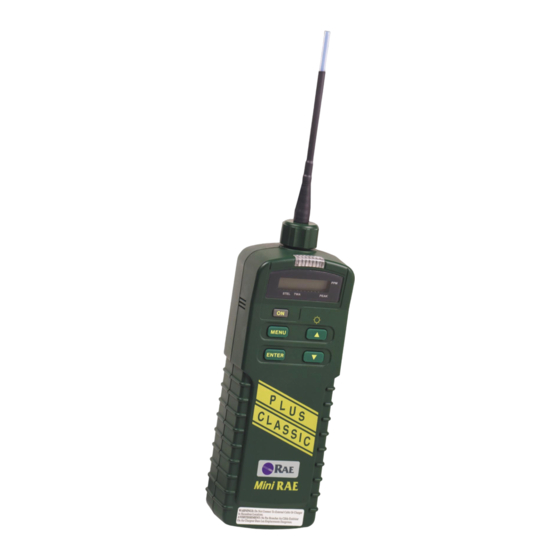
SECTION 2 OPERATION OF MINIRAE PLUS 2.1 Physical Description Figure 2.1 shows the main components of the MiniRAE Plus Professional PID Unit which includes : • 5 keys for user to interact with the unit : power key and 2 operation keys for normal operation;... - Page 21 SECTION 2 OPERATION OF MINIRAE PLUS The operation details are explained in the following sections. Figure 2.1 Major parts of the MiniRAE Plus 2 - 3...
-
Page 22: Two Mode Of Operation
SECTION 2 OPERATION OF MINIRAE PLUS 2.2 Two Modes of Operation The MiniRAE Plus PGM-76 Profession PID unit offers two different operating modes: 1) Industrial Hygiene Mode ( simplified as Hygiene Mode): In this mode of operation, the unit measures the air sample once each second and compares it with a preset peak alarm limit. - Page 23 SECTION 2 OPERATION OF MINIRAE PLUS sets of sample readings with 24 hour time stamps can be recorded in this mode. Selection of Operation Mode: Users can configure the instrument to be in either one of the two operating modes using a software package - "ProRAE -76" which is supplied with the Basic Kit of MiniRAE Plus.
-
Page 24: Keys And Display
SECTION 2 OPERATION OF MINIRAE PLUS 2.3 Keys and Display Figure 2.2 shows the LCD display and the keypad on the front panel of the unit. The function of the 5 keys during normal operation are summarized bellow: STEL TWA PEAK MENU ENTER... - Page 25 SECTION 2 OPERATION OF MINIRAE PLUS Table 2.1 Function in Normal Operation [on] -Toggle on/off the power; [up] -Toggle on/off the back light [down] -Choose display readings [enter] -Confirm to turn off the power* [menu] -Enter into programming task** Caution: entering programming task will interrupt normal gas monitoring operation of the unit.
- Page 26 SECTION 2 OPERATION OF MINIRAE PLUS The MiniRAE Plus Professional PID includes a 7-digit LCD display with 4 labels of STEL, TWA, PEAK, and PPM marked on the window, as shown in Figure 2.2. The display will show the following five types of readings: •...
-
Page 27: Power On/Off
SECTION 2 OPERATION OF MINIRAE PLUS 2.4 Power On/Off To turn on the MiniRAE Plus Professional PID Unit, press [on] key. The audio buzzer will beep once and the display will show "HG- x.xx" or "Su- x.xx" to indicate the operating mode and software version number. -
Page 28: Display Readings
SECTION 2 OPERATION OF MINIRAE PLUS 2.5 Display Readings The MiniRAE Plus Professional PID Unit can display five different readings: instantaneous gas concentration , STEL*, TWA, peak and battery voltage. Here is a brief explanation of each reading: 1) The instantaneous reading is the gas concentration in parts per million (ppm). - Page 29 SECTION 2 OPERATION OF MINIRAE PLUS The reading is updated at one second interval and is shown as "xxx.x" with a small arrow cursor pointing to the "PEAK" label on the LCD window. In Survey mode, the peak reading is the peak gas reading during the previous sampling period.
-
Page 30: Alarm Signal
SECTION 2 OPERATION OF MINIRAE PLUS 2.6 Alarm Signal The built-in microcomputer constantly updates and monitors real time gas concentration and compares it with the programmed alarm limits (TWA, STEL, and peak limits for Hygiene Mode, low and high limits for Survey Mode). Whenever the concentration exceeds any of the preset limits, the alarm buzzer and red flashing LED will be activated immediately to warn user of the alarm condition. - Page 31 SECTION 2 OPERATION OF MINIRAE PLUS operation of the unit immediately and follow the troubleshooting guide in section 9 to diagnose the problem. In Survey Mode, the alarm signal is proportional to the magnitude of the gas concentration. Therefore, when gas concentration exceeds preset limits, the alarm signal may vary from a "single beep"...
-
Page 32: Preset Alarm Limits And
SECTION 2 OPERATION OF MINIRAE PLUS 2.7 Preset Alarm Limits and Calibration The MiniRAE Plus Professional PID Unit is factory calibrated with standard isobutylene gas, and is programmed with default alarm limits as listed below. Refer to section 4 and 5 for programming procedures if new calibration or new alarm limits are required. -
Page 33: Datalogging
SECTION 2 OPERATION OF MINIRAE PLUS 2.8 Datalogging The MiniRAE Plus Professional PID Unit is capable of recording crucial data during normal operation. The recorded data can be down loaded to Personal Computer later on for record keeping or report generation. The data recorded in two operating modes are different: Hygiene Mode: In Hygiene Mode, MiniRAE Plus Professional PID Unit... - Page 34 SECTION 2 OPERATION OF MINIRAE PLUS In Survey Mode, the MiniRAE Plus Professional Unit will allow users to record up to 50 readings of average or peak gas concentration over a specified sampling period. In addition, a time stamp and a site number will also be recorded together with each reading.
- Page 35 SECTION 2 OPERATION OF MINIRAE PLUS When datalogging is in progress during a sampling period, the unit will not respond to [menu] key input to prevent disruption of the datalogging operation. A small letter "d" will also flash next to the site number to indicate that the datalogging is in progress.
-
Page 36: Turn Off Buzzer
SECTION 2 OPERATION OF MINIRAE PLUS 2.9 Turn Off Buzzer In Hygiene Mode, the alarm buzzer can be turned off for 60 seconds by pressing [enter] key. After the 60 second time interval expires, the buzzer will resume if the alarm condition still exists. -
Page 37: Back Light
SECTION 2 OPERATION OF MINIRAE PLUS 2.10 Back Light The LCD display is equipped with a red LED back light to assist the readings under poor lighting conditions. This back light can be turned on by pressing the [up] key. When the back light is already on, press [up] key will turn it off. -
Page 38: Special Power-On Sequence
SECTION 2 OPERATION OF MINIRAE PLUS 2.11 Special Power-on Sequence In MiniRAE Plus Professional PID Unit, all data are automatically retained in non-volatile memory even if the power is turned off. Users can therefore turn off the unit and turn it back on to resume the operation without losing previously stored data during normal operation. -
Page 39: Diagnostic Power-On Sequence
SECTION 2 OPERATION OF MINIRAE PLUS 2.12 Diagnostic Power-on Sequence The MiniRAE Plus Professional PID Unit offers a special diagnostic power on sequence to allow user to read "raw" (or un-calibrated) instrument readings during zero gas calibration procedure. This feature can provides additional information to users regarding the sensor performance. -
Page 40: Disconnect Battery
SECTION 2 OPERATION OF MINIRAE PLUS 2.13 Disconnect Battery The MiniRAE Plus Professional PID Unit provides a mechanical switch to allow user to disconnect the battery from the unit. This is to prevent the battery from being deeply discharged when the unit is placed on the shelf or during shipment. -
Page 41: Operation Of Accessories
SECTION 3 OPERATION OF ACCESSORIES 3.0 OPERATION OF ACCESSORIES There are a number of accessories for MiniRAE Plus Professional PID Unit: • 110 V AC charging adapter • Gas outlet port adapter and sample collection Tedlar bag • Remote access probe ( 8 ft.) •... -
Page 42: Charging Of Minirae Plus
SECTION 3 OPERATION OF ACCESSORIES 3.1 Charging of the MiniRAE Plus On the rear side of the MiniRAE Plus Professional PID Unit, there is a battery charging jack which is normally covered by a protective rubber cover. Open the rubber cover and connect the AC adapter (or the automotive DC charging adapter, depending on the power source) to the charging jack. - Page 43 SECTION 3 OPERATION OF ACCESSORIES As the battery becomes older or operated under adverse conditions, the battery capacity will be reduced significantly. The battery of the MiniRAE Plus unit will be drained slowly even if the unit is turned off. If the unit has not been charged for 4-5 days, the battery voltage will be low.
-
Page 44: Sample Gas Collection
SECTION 3 OPERATION OF ACCESSORIES 3.2 Sample Gas Collection On the right side of the MiniRAE Plus Professional PID Unit, there is a gas outlet port where the gas sample can be collected after going through the sensor module and pump unit. A gas outlet port adapter with 2 ft. -
Page 45: Remote Access Probe
SECTION 3 OPERATION OF ACCESSORIES 3.3 Remote Access Probe A remote access probe is available as an optional accessory for the MiniRAE Plus Professional PID Unit. This probe is constructed with an aluminum telescoping pointer and 6.5 ft. Teflon tubing. The telescoping pointer allows the probe unit to be stored in a compact space when not in use and conveniently extended into a 4 ft. -
Page 46: Audio Interface Adapter And Earphone
SECTION 3 OPERATION OF ACCESSORIES 3.4 Audio Interface Adapter and Earphone On the rear side of the MiniRAE Plus Professional PID Unit, there is an 8 pin round multi-interface jack which is normally covered by a protective rubber cover. An audio interface adapter cable and a small earphone is available as an optional accessory for the MiniRAE Plus Professional PID Unit. - Page 47 SECTION 3 OPERATION OF ACCESSORIES Audio alarm signal The audio alarm signal consists of a series of 2 kHz pulses appearing at pin 7 of the multi-interface jack. The duty cycle of the signal is 50%. Figure 3.1 shows the specification and waveform of the alarm signal: Alarm signal specification: voltage :...
- Page 48 SECTION 3 OPERATION OF ACCESSORIES 3.5 Analog Interface Adapter An analog interface adapter cable is available as an optional accessory for the MiniRAE Plus Professional PID Unit. Open the rubber cover and connect the interface cable to the multi- interface jack. The analog signal output from the sensor module ( 0 - 1 V ) is brought out through this interface cable.
-
Page 49: Analog Signal Output
SECTION 3 OPERATION OF ACCESSORIES Note: in order to prevent overloading of the analog output signal, when connecting to external device, only high impedance inputs should be used. Multi-interface pin assignment The multi-interface jack at the bottom of the unit is a circular DIN receptacle with 8 holes. - Page 50 SECTION 3 OPERATION OF ACCESSORIES A water trap disk device is offered as an accessory to the MiniRAE Plus Professional PID unit. This device is constructed with a polypropylene housing and PTFE membrane filter. This device is to be inserted into the front end of the gas inlet probe during operation.
-
Page 51: Dilution Probe
SECTION 3 OPERATION OF ACCESSORIES 3.7 Dilution Probe A dilution probe device is offered as an accessory to the MiniRAE Plus Professional PID unit. This device mixes one part of incoming gas sample with 9 parts of clean air to dilute the concentration of the gas sample by 10 times. - Page 52 SECTION 3 OPERATION OF ACCESSORIES display. This reading should be very close to 1/10 of the actual gas value. If the value is off a little bit, use the Allen wrench to adjust the set screw. Note: user has to loosen the lock nut first, then turn the set screw.
-
Page 53: Uv Attenuator Ring
SECTION 3 OPERATION OF ACCESSORIES adapter from the body. Replace the membrane filter. Make sure that the Teflon washer remains inside the cavity. Replace the tube adapter. (2) Replace charcoal filter : The charcoal filter needs to be replaced every six months or sooner. - Page 54 SECTION 3 OPERATION OF ACCESSORIES longer operating life. However, such a strong lamp may cause the sensor to saturate when high concentration of vapor is measured. When to use the Attenuator Ring ? When high concentration of vapor ( greater than 500 ppm ) is expected during normal operation.
- Page 55 SECTION 3 OPERATION OF ACCESSORIES Installation of the Attenuator Ring : To install the ring, open the sensor block from the lamp housing, put the ring on the 0.5" hole opening on the sensor block. Then close the lamp housing, making sure that the lamp window is pressed against the ring.
- Page 56 SECTION 3 OPERATION OF ACCESSORIES This page is intentionally left blank 3 - 16...
-
Page 57: Programming In Hygiene Mode
SECTION 4 PROGRAMMING IN HYGIENE MODE 4.0 PROGRAMMING IN HYGIENE MODE The MiniRAE Plus Professional PID Unit is built with a microcomputer to provide programming flexibility. In Hygiene Mode operation, authorized users can re-calibrate the unit, change the gas concentration alarm limits and set the date and time of the internal real time clock. -
Page 58: Menu Options
SECTION 4 PROGRAMMING IN HYGIENE MODE 4.1 Menu Options The Hygiene Mode programming provides ten menu options as shown in Table 4.1 below. The first menu option allow entry into the programming menu by keying a four digit password (Note: this menu option will be displayed for level 1 security only). - Page 59 SECTION 4 PROGRAMMING IN HYGIENE MODE Verify password Pd-0000 Set STEL limit SA xxx.x 0 1 2 Set TWA limit tA xxx.x 0 1 2 Set Peak limit PA xxx.x 0 1 2 Zero gas calibration C0 xxx.x Standard gas value C1u xxx.x Standard gas calibration C1 xxx.x...
-
Page 60: Keys For Programming Task
SECTION 4 PROGRAMMING IN HYGIENE MODE 4.2 Keys for Programming Task The five keys perform a different set of functions during the programming task as summarized below. Table 4.2 Function in Programming Task [on] This key does not function during programming task [up] Increment numerical value for data entry... -
Page 61: Entering Into Programming Task
SECTION 4 PROGRAMMING IN HYGIENE MODE 4.3 Entering into Programming Task CAUTION Do not operate programming task in the potentially hazardous environments that require continuous protection. The real time monitoring of gas concentration will be interrupted during programming task. 1. The Professional PID Unit should already be turned on before entering the programming task. - Page 62 SECTION 4 PROGRAMMING IN HYGIENE MODE (Note 2: For added security, "0000" is always displayed instead the actual password at this step.) 3. If the correct digit value is not "0", use [up] arrow key or [down] arrow key to increase or decrease the digit value. Then press [enter] key to confirm the value.
-
Page 63: Set Stel Alarm Limit
SECTION 4 PROGRAMMING IN HYGIENE MODE 4.4 Set STEL Alarm Limit 1. "Set STEL alarm limit" option is the 2nd menu option in Table 4.1. - Display shows "SA xxx.x" with the left- most digit flashing, where "xxx.x" is the previously stored STEL alarm limit. -
Page 64: Set Twa Alarm Limit
SECTION 4 PROGRAMMING IN HYGIENE MODE 4.5 Set TWA Alarm Limit 1. Set "TWA alarm limit" option is the 3rd menu option in Table 4.1. - Display shows "tA xxx.x" with the left- most digit flashing, where "xxx.x " is the previously stored TWA alarm limit. -
Page 65: Set Peak Alarm Limit
SECTION 4 PROGRAMMING IN HYGIENE MODE 4.6 Set Peak Alarm Limit 1. Set "Peak alarm limit" option is the 4th menu option in Table 4.1. - Display shows "PA xxx.x" with the left- most digit flashing, where "xxx.x " is the previously stored Peak alarm limit. -
Page 66: Calibration Of Minirae Plus
SECTION 4 PROGRAMMING IN HYGIENE MODE 4.7 Calibration of MiniRAE Plus In the Hygiene Mode, the user may re-calibrate the MiniRAE Plus Professional PID Unit. This is a two-point calibration process using "zero gas" and standard reference gas. First, a "zero gas"... -
Page 67: Zero Gas Calibration
SECTION 4 PROGRAMMING IN HYGIENE MODE 4.7.1 Zero Gas Calibration The organic vapor zeroing kit, see Figure 4.1, is supplied to perform zero gas calibration. This kit consists of • Calibration adapter to link up with the gas inlet tube of the Professional PID Unit •... - Page 68 SECTION 4 PROGRAMMING IN HYGIENE MODE Zero Gas Calibration Procedure 1. "Zero gas calibration" option is the 5th menu option in Table 4.1. - Display shows "C0 xxx.x" where "xxx.x" is the gas reading based on current calibration of the instrument. Note: this reading may not be zero due to back ground gas concentration, dirty charcoal filter or instrument drift .
- Page 69 SECTION 4 PROGRAMMING IN HYGIENE MODE 4. If this reading is not zero, press [enter] key to zero it. If the reading still shows a small value after a few seconds, press [enter] key again to zero it. Repeat this process until the reading is stabilized around zero or 0.1 ppm.
-
Page 70: Enter Standard Calibration Gas Value
SECTION 4 PROGRAMMING IN HYGIENE MODE 4.7.2 Enter Standard Calibration Gas Value 1. "Enter standard gas value" option is the 6th menu option in Table 4.1. - Display shows "C1u xxx.x" where "xxx.x" is the previously stored standard calibration gas value. For example, "C1u 100.0"... - Page 71 SECTION 4 PROGRAMMING IN HYGIENE MODE " GAS On" to remind user to turn on the standard calibration gas bottle now. After the gas bottle is turned on, press [enter] key to continue the standard gas calibration procedure as described in section 4.7.3. 5.
-
Page 72: Standard Reference Gas Calibration
SECTION 4 PROGRAMMING IN HYGIENE MODE 4.7.3 Standard Reference Gas Calibration Figure 4.2 shows the typical installation of standard reference gas calibration. It includes: • Calibration adapter with flow controller • Reference gas bottle of 100 ppm isobutylene Figure 4.2 Standard reference gas calibration setup 4 - 16... - Page 73 SECTION 4 PROGRAMMING IN HYGIENE MODE Standard Gas Calibration Procedure 1. Insert the calibration adapter into the gas inlet tube of the Personal PID Unit, and connect the calibration adapter with the standard gas bottle, as shown in Figure 4.2. 2.
- Page 74 SECTION 4 PROGRAMMING IN HYGIENE MODE standard gas value. This completes the standard gas calibration procedure. 3. Press [menu] key to exit the standard gas calibration procedure and move to next menu item. 4. Turn the flow controller knob fully clockwise to turn off the flow of gas.
- Page 75 SECTION 4 PROGRAMMING IN HYGIENE MODE higher energy lamp. The second reason is that the UV light intensity of the lamp is weak. In this case, replace the UV lamp with a newer and stronger one. 4 - 19...
-
Page 76: Alternative Calibration Methods
SECTION 4 PROGRAMMING IN HYGIENE MODE 4.7.4 Alternative Calibration Methods There are two alternative calibration methods of the reference gas which often are used by some users. These methods are described briefly here: A) Sampling Bag Calibration method: First, fill a Tedlar sampling bag with the reference gas from a standard gas bottle. - Page 77 SECTION 4 PROGRAMMING IN HYGIENE MODE slowly to increase the gas flow from the bottle until the ball start to float up in the tube. At this point, the flow rate of the regulator matches the flow rate of the sampling pump. Again, the adjustable flow regulator calibration method allows a better matching of the flow rate between the regulator and the sampling pump of MiniRAE Plus.
-
Page 78: Calibration For Other Gases
SECTION 4 PROGRAMMING IN HYGIENE MODE 4.7.5 Calibration for Other Gases It is often impractical to carry a range of different standard gases into the field for calibration. If the type of the organic vapor to be measured in the field is known and the relative sensitivity of this gas compared to the standard reference gas ( such as 100 ppm isobutylene ) for the PID instrument is available, then one can calibrate the instrument using a standard... - Page 79 SECTION 4 PROGRAMMING IN HYGIENE MODE 1) Direct reading of a specific gas in ppm: step 1: Obtain the calibration factor of a given organic vapor. For example, benzene has a calibration factor of 0.57 relative to the standard 100 ppm isobutylene gas. step 2: Multiply the standard calibration gas value ( such as 100 ppm of isobutylene) by the calibration factor to obtain a compensated calibration standard value for the given gas, i.e.
- Page 80 SECTION 4 PROGRAMMING IN HYGIENE MODE step 3: When exposed to a specific gas, multiply the instrument reading by the calibration factor manually. The result is the calculated value in ppm for the specific gas. For example, if the instrument is calibrated using isobutylene gas. When exposed to 100 ppm benzene gas, it reads 175.4.
-
Page 81: Clear Data
SECTION 4 PROGRAMMING IN HYGIENE MODE 4.8 Clear Data The Professional PID unit calculates and stores the values of TWA, STEL, Peak concentration and 12 hours of STEL readings taken at 15 minutes interval ( a total of 51 readings). In addition, the time stamps which indicate: when the unit was last turned on and off, when the peak occurred and when the TWA alarm occurred (if any) will also be recorded. -
Page 82: Set Hour And Minute
SECTION 4 PROGRAMMING IN HYGIENE MODE 4.9 Set Hour and Minute In Hygiene Mode, users are allowed to change the hour and minute of the built-in real time clock. A 24 hour format is used for the hour value. 1. "Set hour and minute" option is the 9th menu option in Table 4.1. -
Page 83: Set Month And Date
SECTION 4 PROGRAMMING IN HYGIENE MODE 4.10 Set Month and Date In Hygiene Mode, users are allowed to change the month and date of the built-in real time clock. 1. Set "month and date" option is the 10th menu option in Table 4.1. -
Page 84: Set Security Level
SECTION 4 PROGRAMMING IN HYGIENE MODE 4.11 Set Security Level In Hygiene Mode, authorized users are allowed to set the security level from the PC so that three levels of different data protection can be setup for the operator of the instrument. 1) level 0 security: in this level, users can view three alarm limits and the current time and date in programming task. - Page 85 SECTION 4 PROGRAMMING IN HYGIENE MODE File sub-menu, then choose Instrument Setup function from the Options sub-menu. The PC display will show a dialog box as shown in Screen 6.9. Step 2: Move cursor to the security level section of the menu and choose one of the three security levels by clicking the mouse on one of the three radio buttons.
-
Page 86: Change Password
SECTION 4 PROGRAMMING IN HYGIENE MODE 4.12 Change Password In Hygiene Mode, authorized users are allowed to set a password for the instrument so that when level 1 security is selected for the instrument, users have to enter a valid password in order to enter the programming task. -
Page 87: Programming In Survey Mode
SECTION 5 PROGRAMMING IN SURVEY MODE 5.0 PROGRAMMING IN SURVEY MODE The MiniRAE Plus Professional PID Unit is built with a microprocessor to provide programming flexibility. In Survey Mode operation, users can choose a new site number, select one of two calibration data, re-calibrate the unit, change the sampling period, clear data memory, change the gas concentration alarm limits, and change time and date of the real time clock. -
Page 88: Menu Options
SECTION 5 PROGRAMMING IN SURVEY MODE 5.1 Menu Options The programming menu for Survey Mode includes 11 menu options as shown in the Table 5.1 below. User enters the programming menu by pressing [menu] key. The first menu option will appear in the display. User can use the other three keys to perform the desired programming tasks. - Page 89 SECTION 5 PROGRAMMING IN SURVEY MODE Table 5.1 Menu Option Display Site selection SItE xx Select calibration data GAS - x Zero gas calibration C0 xxx.x Enter standard gas value C1u xxx.x Standard gas calibration C1 xxx.x Set sampling period (in seconds) SP xxxx Clear all data Clr ALL...
-
Page 90: Keys For Programming Task
SECTION 5 PROGRAMMING IN SURVEY MODE 5.2 Keys for Programming Task The operation of the five keys during the programming task in Survey Mode is identical to that of Hygiene Mode. Table 5.2 Function in Programming Task [on] This key does not function during programming task [up] Increment numerical value for data entry... -
Page 91: Entering Into Programming Task
SECTION 5 PROGRAMMING IN SURVEY MODE 5.3 Entering into Programming Task CAUTION Do not perform programming task in the potentially hazardous environments that require continuous protection. The real time monitoring of gas concentration will be interrupted during programming task. 1. The MiniRAE Plus Professional PID Unit should already be turned on already before entering the programming task. -
Page 92: Select Site Number
SECTION 5 PROGRAMMING IN SURVEY MODE 5.4 Select Site Number 1. The first menu option ( item 1 in Table 5.1) is to allow users to select a new site number. - Display shows the following message "SItE xx". where xx is the current site number. 2 Press [up] key once to increase the site number by one. -
Page 93: Select Calibration Data
SECTION 5 PROGRAMMING IN SURVEY MODE 5.5 Select Calibration Data In Survey Mode, users are allowed to select anyone of the two previously stored gas calibration data to be used for current gas measurement. These two gas calibration data are identified by a single digit gas number 1 or 2. -
Page 94: Calibration Of Minirae Plus
SECTION 5 PROGRAMMING IN SURVEY MODE 5.6 Calibration of MiniRAE Plus In Survey Mode, user is allowed to select one of two previously stored calibration data. It is therefore also necessary to calibrate and store two sets of calibration data. The calibration procedure for either one of the two gases is identical to that of the Hygiene Mode. -
Page 95: Set Sampling Period
SECTION 5 PROGRAMMING IN SURVEY MODE 5.7 Set Sampling Period Users are allowed to select a sampling period for the datalog operation. This period can be between 1 second to 9999 seconds. 1. "Set Sampling Period" option is the 6th menu option in Table 5.1. -
Page 96: Clear Data
SECTION 5 PROGRAMMING IN SURVEY MODE 5.8 Clear Data The Professional PID unit stores up to 50 single readings of the time weighted average of the gas concentration. The time (hour and minute) at the end of each sampling period will also be recorded for each reading. -
Page 97: Set Low Alarm Limit
SECTION 5 PROGRAMMING IN SURVEY MODE 5.9 Set Low Alarm Limit In Survey Mode, users are allowed to define a low alarm limit. When gas concentration is bellow this limit, the alarm will not be activated. The minimum value for this low limit is zero. 1. -
Page 98: Set High Alarm Limit
SECTION 5 PROGRAMMING IN SURVEY MODE 5.10 Set High Alarm Limit In Survey Mode, users are allowed to define a high alarm limit. When gas concentration exceeds this limit, the alarm will be activated at the highest frequency. The high limit and low limit also define the range whereby the alarm signal will vary its frequency. -
Page 99: Set Hour And Minute
SECTION 5 PROGRAMMING IN SURVEY MODE 5.11 Set Hour and Minute In Survey Mode, users are allowed to set the hour and minute value of the real time clock. The procedures for setting the hour and minute value are identical to that of Hygiene Mode. Please refer to section 4.9 for operation details. -
Page 100: Select Datalog Option
SECTION 5 PROGRAMMING IN SURVEY MODE 5.13 Select Datalog Option In Survey Mode, authorized users are allowed to select one of the following two different datalog options from the PC: 1) manual sampling option: in this option, users have to press [enter] key to start each sampling period. - Page 101 SECTION 5 PROGRAMMING IN SURVEY MODE Step 1: From the main menu of the ProRAE-76 software, Open the Survey Mode configuration file (survey.CFG) from the File sub-menu, then choose Instrument Setup function from the Options sub-menu. The PC display will show a dialog box as shown in Screen 6.10.
-
Page 102: Select Data Type Option
SECTION 5 PROGRAMMING IN SURVEY MODE 5.14 Select Data Type Option In Survey Mode, authorized users are allowed to select one of the following two different data type to be stored from the PC: 1) peak data option: in this option, the peak value during each sampling period is stored. - Page 103 SECTION 5 PROGRAMMING IN SURVEY MODE Step 2: Move cursor to the data type option section of the menu and choose one of the two data type options by clicking the mouse on one of the two radio buttons. Step 3: After the instrument configuration is completed, send it to the instrument as described in section 6.9.
- Page 104 SECTION 5 PROGRAMMING IN SURVEY MODE This page is intentionally left blank 5 - 18...
-
Page 105: Computer Interface For Minirae Plus
SECTION 6 COMPUTER INTERFACE FOR MINIRAE 6.0 COMPUTER INTERFACE FOR MINIRAE PLUS Each MiniRAE Plus Professional PID kit is shipped with an integral software package, called ProRAE-76 and a computer interface cable. This software package offers additional capabilities to the basic MiniRAE Plus PID instrument to enhance its functionality. - Page 106 SECTION 6 COMPUTER INTERFACE FOR MINIRAE Due to hardware differences between MiniRAE (model PGM- 75) and MiniRAE Plus (model PGM-76IS and PGM-76), the ProRAE-76 software package is not compatible with the existing ProRAE-75 software package. The ProRAE-76 will only work with MiniRAE Plus product line while the ProRAE- 75 will only work with MiniRAE product line.
-
Page 107: Installation Of Prorae-76
[enter] key on the keyboard or click [OK] button on the menu. The ProRAE-76 software package will be installed automatically under a newly created directory - called ProRAE76. After the software is installed successfully, a RAE logo icon will appear in the ProRAE-76 Application Program Group. -
Page 108: Connecting Minirae Plus To Pc
SECTION 6 COMPUTER INTERFACE FOR MINIRAE Connecting MiniRAE Plus to PC The basic kit of MiniRAE Plus Professional PID unit is supplied with a PC interface adapter cable. Connect the round 8 pin plug at one end of the cable to the multi-interface jack at the rear side of the PID unit. -
Page 109: Starting Prorae-76
SECTION 6 COMPUTER INTERFACE FOR MINIRAE Starting ProRAE-76 After the ProRAE-76 software is successfully installed , there will be an application icon that shows a RAE logo inside the ProRAE-76 Application Program Group of the Program Manager. To start the ProRAE-76 program, double click the RAE logo icon. - Page 110 SECTION 6 COMPUTER INTERFACE FOR MINIRAE To invoke a function within a sub-menu, position the mouse cursor at the title of each sub-menu and click the left button of the mouse to pull down the sub-menu. Move the cursor to the desired function in the sub-menu and click the left button of the mouse to activate the function.
-
Page 111: Receive Data From Minirae Plus
SECTION 6 COMPUTER INTERFACE FOR MINIRAE Receive Data from MiniRAE Plus In order to receive data from MiniRAE Plus, users first have to connect the MiniRAE Plus unit to a PC as described in section 6.2. From the main menu of ProRAE-76 software, select the Receive function from the Communication sub-menu or click the Receive icon (left arrow with "Recv"... -
Page 112: View Data
SECTION 6 COMPUTER INTERFACE FOR MINIRAE 6.5 View Data After the datalog results are transferred from MiniRAE Plus Professional PID Unit into PC, users can view the data in graphic or text format. From the main menu, select Plot function from View sub-menu for a graphic display of the data. Screen 6.3 shows a typical graphic display. - Page 113 SECTION 6 COMPUTER INTERFACE FOR MINIRAE Screen 6.4 Set View Range Dialog Box Note: if users enter a new start or stop hour for viewing which is outside the actual datalog start and stop time, an error message will appear. Users should always set the start and stop hour for viewing to be within the actual datalog start and stop hour.
- Page 114 SECTION 6 COMPUTER INTERFACE FOR MINIRAE Note : in Survey mode, the x- axis of the graphic data display may not reflect the actual time if the data was not collected in a continuous sampling mode. The graphic data is plotted based on the assumption that the first data point is the starting time, and each subsequent data point is collected after one sampling period.
- Page 115 SECTION 6 COMPUTER INTERFACE FOR MINIRAE Users can select the Data function from View sub-menu to see a text display of the data file. Screen 6.6 Text Data in Text Window The text data is displayed in a text window. Screen 6.6 shows a typical text data displayed in a text window.
- Page 116 SECTION 6 COMPUTER INTERFACE FOR MINIRAE The alarm status column will display a letter "H" or "L" if High or Low alarm limit is exceeded. Note: the text data can be saved as text file ( ASCII characters ) by high light the area of the text window and click the Copy to Clipboard button.
-
Page 117: Save Data File
SECTION 6 COMPUTER INTERFACE FOR MINIRAE 6.6 Save Data File After viewing the data results, it may be desirable to save the data file for future use. Users have to select Save As function from the File sub-menu or click the Save As icon ( a disk ) from the tool bar. - Page 118 SECTION 6 COMPUTER INTERFACE FOR MINIRAE After viewing the data results, it is possible to print the data to a printer in order to obtain a hard copy of the text or graphic data report. To print the graphic data, choose the Plot function form the View sub-menu first.
-
Page 119: Configure Minirae Plus From Pc
SECTION 6 COMPUTER INTERFACE FOR MINIRAE Configure MiniRAE Plus from PC The ProRAE-76 software allow users to configure the MiniRAE Plus Professional PID Unit for Hygiene or Survey Mode operation, set alarm levels, select security level and password for Hygiene Mode, and select datalog options for Survey Mode from PC and send the configuration information to the unit when it is ready. - Page 120 SECTION 6 COMPUTER INTERFACE FOR MINIRAE There should be two or more configuration files in the file list. Each configuration file has a file extension of .CFG. There are two generic configuration files supplied with ProRAE-76 software: HYGIENE.CFG and SURVEY.CFG. Choose either the SURVEY.CFG or HYGIENE.CFG by highlighting the file name and depress [Enter] key or click [OK] button.
- Page 121 SECTION 6 COMPUTER INTERFACE FOR MINIRAE Screen 6.9 Hygiene Mode Configuration Users can now move the cursor to each data entry box to fill in the information, such as Operator ID, Site Name, Alarm Limits, etc. User can also click on the radio button to choose security levels, datalog options or data type, etc.
- Page 122 SECTION 6 COMPUTER INTERFACE FOR MINIRAE information are entered, depress [Enter] key or click [OK] button. Screen 6.10 Survey Mode Configuration Note: the Operator ID, Site Name and Year information is only used for reference purpose. It is not sent to the MiniRAE Plus instrument.
- Page 123 SECTION 6 COMPUTER INTERFACE FOR MINIRAE Saving calibration and clock data: In both Hygiene and Survey Mode configuration dialog box, there is a check box at the bottom of the dialog box : " [ ] save calibration and clock data". If this box is checked, then the calibration data, password and real time clock information will be preserved in the unit so that users do not need to re-calibrate or re-enter password and real time clock information after a...
-
Page 124: Send Configuration To Minirae Plus
SECTION 6 COMPUTER INTERFACE FOR MINIRAE 6.9 Send Configuration to MiniRAE Plus In order to send the configuration information to the MiniRAE Plus Professional PID Unit, select the Send function from the Communication sub-menu or click the Send icon (right arrow with "Send"... -
Page 125: Save Configuration File
SECTION 6 COMPUTER INTERFACE FOR MINIRAE 6.10 Save Configuration File In order to save the configuration information for future use, users can select Save As function from the File sub-menu or click the Save As icon ( a disk ) from the tool bar. A dialog box will appear, similar to Screen 6.7. -
Page 126: Other Functions Of Prorae-76
SECTION 6 COMPUTER INTERFACE FOR MINIRAE 6.11 Other Functions of ProRAE-76 1) Exit ProRAE-76 Program: To exit the ProRAE-76 program, choose Exit function from the File sub-menu. 2) Copy to Clipboard: Choose Copy to Clipboard function from the Options sub- menu. -
Page 127: Dos Version Of Prorae-76
SECTION 6 COMPUTER INTERFACE FOR MINIRAE 6.12 DOS Version of ProRAE-76 A DOS version of the ProRAE-76 software is included in this package. It can be installed on any PC compatible computers using DOS 5.0 and later version of DOS with 640 K byte memory and 1 M byte of hard disk space. -
Page 128: Installation Of Prorae-76 For Dos
SECTION 6 COMPUTER INTERFACE FOR MINIRAE 6.12.1 Installation of ProRAE-76 for Insert the ProRAE-76 diskette supplied with the basic kit into the "A" drive. This is the first disk drive on most PC which usually accept 3.5" diskette. ( If the A: drive accepts 5.25" floppy, please call the factory for a free copy of the ProRAE- 76 in 5.25"... -
Page 129: Operation Of Prorae-76 For Dos
SECTION 6 COMPUTER INTERFACE FOR MINIRAE 6.12.2 Operation of ProRAE-76 for Step 1: start ProRAE-76 for DOS program: Type "prorae" followed by [enter] key to start the program: C:\PRORAE> prorae [enter] Users should see following main menu: ******************************************** ProRAE-76 DOS version * for MiniRAE Plus Professional PID Unit * V 2.30 Date: 3/22/95... - Page 130 SECTION 6 COMPUTER INTERFACE FOR MINIRAE To run the program directly from floppy drive, place the diskette into A: drive, type C:\ a: [enter] A:\ cd prorae [enter] A:\PRORAE\ prorae [enter] Step 2: connect MiniRAE Plus Connect the MiniRAE Plus Professional PID unit to the parallel port of the PC, as described in section 6.2.
- Page 131 SECTION 6 COMPUTER INTERFACE FOR MINIRAE E E P R O M - U T I L I T Y for Xicor 24(L)Cxx Calling format : - Burn : sdt_xic LPT B filespec [messagefilespec] - Read : sdt_xic LPT R filespec [messagefilespec] Verify : sdt_xic LPT V filespec [messagefilespec] - Clear : sdt_xic LPT C [messagefilespec] If messagefilespec not specified then output to...
- Page 132 SECTION 6 COMPUTER INTERFACE FOR MINIRAE ==>task completed successfully type any key to continue ... Type any key, the screen will return to main menu. Disconnect the interface cable, the MiniRAE Plus is now ready for Survey Mode operation. If there is any problem during the communication, there will be an error message: Error 8 ==>...
- Page 133 SECTION 6 COMPUTER INTERFACE FOR MINIRAE 2) Configure for Hygiene Mode: To configure the MiniRAE Plus-76 to be in Hygiene Mode, type "2a", "2b" or "2c", depending on the choice of the security level, and followed by [enter] key. Type 2a : level 0 security ( no change allowed) : level 1 security ( change allowed, need to enter a password )
- Page 134 SECTION 6 COMPUTER INTERFACE FOR MINIRAE ==>task completed successfully type any key to continue ... Type any key, the screen will return to main menu. Disconnect the interface cable, the MiniRAE Plus is now ready for Hygiene Mode operation. Save calibration and clock data: After a new configuration is sent to the MiniRAE Plus, the previously stored measurement data will all be erased and the default alarm limits will be used.
- Page 135 SECTION 6 COMPUTER INTERFACE FOR MINIRAE To receive data from MiniRAE Plus, type "3" and followed by [enter] key. The display will show: Receiving Data From MiniRAE Plus ..E E P R O M - U T I L I T Y for Xicor 24(L)Cxx Calling format : - Burn : sdt_xic LPT B filespec [messagefilespec] - Read : sdt_xic LPT R filespec [messagefilespec]...
- Page 136 SECTION 6 COMPUTER INTERFACE FOR MINIRAE This text window shows the data just received from the MiniRAE Plus. Use [up] and [down] arrow keys or [page up] and [page down] key to browse through the data file. Users can not modify the data at this point. Depress [esc] key to exit the text display window and return to the main menu.
- Page 137 SECTION 6 COMPUTER INTERFACE FOR MINIRAE C:\PRORAE> print survey.txt [enter] Remember to disconnect the MiniRAE Plus unit from the printer port of the PC and connect a parallel printer to it before printing. A simple A-B switch box is recommended to allow users to switch between MiniRAE Plus unit and the printer conveniently.
-
Page 138: Enter Serial Number
SECTION 6 COMPUTER INTERFACE FOR MINIRAE 6.12.3 Enter Serial Number Each MiniRAE Plus Professional PID unit is assigned a unique 6 digits serial number in the factory. This number is shown on the label on the back of the unit. This same number is also stored in the computer memory so that during datalogging operation, the serial number is printed on the data report. - Page 139 Type "ser" followed by [enter] key to start the program: C:\PRORAE> ser [enter] Users should see following main menu: *************************************************** * Rae System PGM-76 PID Serial Number Setup Program Feb 1995 *************************************************** UNIT SERIAL NUMBER IS : XXXXXX IS THIS SERIAL NUMBER CORRECT? (Y/N) Step 3: enter serial number: Type "Y"...
- Page 140 SECTION 6 COMPUTER INTERFACE FOR MINIRAE SET UNIT SERIAL NUMBER == XXXXXX VERIFICATION SUCCESSFUL The program will terminate automatically. 6 - 36...
-
Page 141: Theory Of Operation
SECTION 7 THEORY OF OPERATION 7.0 THEORY OF OPERATION MiniRAE Plus Professional PID unit uses a newly developed Electrodeless discharge UV lamp as the high energy photon source for the PID instrument. A special high efficiency lamp driver is developed to turn on the UV lamp (see Figure 7.1). sensor LCD display UV lamp... - Page 142 SECTION 7 THEORY OF OPERATION A sampling pump continuously draws air sample into the ionization chamber. The ionization chamber for the MiniRAE Plus Professional PID unit is constructed as a small cavity in front of the UV lamp. The electrode is made of wired mesh so that the high energy UV light can shine through the mesh and excite the gas molecules when they across the face of the UV window.
-
Page 143: Maintenance
SECTION 8 MAINTENANCE 8.0 MAINTENANCE As shown in Figure 8.1, the major items of MiniRAE Plus Professional PID Unit that require periodic maintenance are: • Battery • Probe Assembly • Sensor module • Lamp • Sampling Pump Figure 8.1 Main components of MiniRAE Plus Professional PID 8 - 1... -
Page 144: Battery Charging And Replacement
SECTION 8 MAINTENANCE 8.1 Battery Charging and Replacement When the display flashes "bAt" message, the battery requires recharging. The battery may be replaced in the field if required. It is recommended to recharge the MiniRAE Plus Professional PID unit upon returning from field work. A fully charged battery powers MiniRAE Plus Professional PID unit for 10 hours continuous operation. - Page 145 SECTION 8 MAINTENANCE Recharging Professional PID Unit 1. Turn off power of the Professional PID unit. 2. Open the rubber cover on the bottom side of the PID unit and connect the AC adapter (or the automotive DC charging adapter, depending on the power source) to the power jack.
- Page 146 SECTION 8 MAINTENANCE replaced, replace the second battery. Note: there is a real time clock inside the unit. If both batteries are disconnected from the unit at the same time, the real time clock will be disabled. Users have to re-program the real time clock after the batteries are installed (see section 4.9 and 4.10 on how to program real time clock ).
-
Page 147: Filter Replacement
SECTION 8 MAINTENANCE 8.2 Filter Replacement During the course of normal operation, dust and residual gas vapor may build up on the membrane filter. The build up rate depends on the working environment and the concentration of the the vapors being sampled. As a guide, it is recommended to replace the membrane filter once a week or when the filter is dirty upon visual inspection. -
Page 148: Sensor Module Cleaning
SECTION 8 MAINTENANCE 8.3 Sensor Module Cleaning During the course of normal operation, a film of gas vapor may build up inside the sensor module. The rate at which the film develops depends on the type and concentration of the vapors being sampled. - Page 149 SECTION 8 MAINTENANCE Sensor Module Cleaning Procedure 1. Turn off power of the MiniRAE Plus Professional PID Unit. 2. Refer to Figure 8.1, unscrew the probe assembly, remove four screws and open the MiniRAE Plus Professional PID Unit. Remove the sensor module by gently pulling the module away from the PCB of the top cover.
- Page 150 SECTION 8 MAINTENANCE leakage and sensor failure. It is recommended to blow dry the sensor block or bake it at 75° C for 5 to 10 minutes to ensure it is fully dried. 6. Replace the membrane filter and small O-ring into the front hole of the sensor block.
- Page 151 SECTION 8 MAINTENANCE free of any "kink" and are not caught under the sensor module. 9. Close the MiniRAE Plus Professional PID Unit covers and replace probe assembly. 8 - 9...
-
Page 152: Probe Assembly Cleaning
SECTION 8 MAINTENANCE 8.4 Probe Assembly Cleaning During the course of normal operation, significant amount of dust and particles can be drawn into the sensor module. A dust filter (steel wool ) is inserted into the cavity at the base of the probe assembly to remove these dust and particles. -
Page 153: Lamp Cleaning And Replacement
SECTION 8 MAINTENANCE 8.5 Lamp Cleaning and Replacement If the lamp does not turn on or there is excessive film build -up on the lamp window, the unit will display a message of " Err xxx.x " to indicate that a cleaning or replacement of the lamp may be required. - Page 154 SECTION 8 MAINTENANCE Lamp Window Cleaning Procedure: For lamps with 10.6 eV or 11.7 eV windows, clean the window surface with anhydrous methanol using a cotton swab. Rub in a circular motion at moderate pressure. After cleaning, hold the lamp up to the light at an angle to detect any remaining film.
-
Page 155: Pump Replacement
SECTION 8 MAINTENANCE 8.6 Pump Replacement The sampling pump is rated for 4000-5000 hours of continuous operation. It will consume higher amount of energy and reduce its sample draw capability significantly when approaching the end of the specified life time of the pump. As a guide, it is recommended to replace the pump at six month intervals, if the instrument is heavily utilized during the period. - Page 156 SECTION 8 MAINTENANCE 6. Replace the probe assembly. 7. Turn on the MiniRAE Plus Unit. Wait for the pump to come on. Check to see if air is drawn into the gas inlet tube. If the pump works correctly, when the gas inlet is blocked by a finger, the pump noise should change and a strong suction force will be felt.
-
Page 157: Troubleshooting
SECTION 9 TROUBLESHOOTING 9.0 TROUBLESHOOTING Table 9.1 Problem Possible Reasons & Solutions Can not turn on Reasons: Bad battery connection power after Discharged battery charging the Defective battery battery Microprocessor hang-up Battery switch is off Solutions: Check battery connection Charge or replace battery Reset microprocessor by turning off and then on battery switch... - Page 158 SECTION 9 TROUBLESHOOTING Problem Possible Reasons & Solutions Reading Reasons: Dirty or wet sensor abnormally Dirty probe assembly high Dirty membrane filter Solutions: Clean sensor module Clean probe assembly Replace membrane filter Use water trap disk Reading Reasons: Lamp dirty or weak abnormally Solutions: Clean or replace lamp (see section 8.4)
- Page 159 SECTION 9 TROUBLESHOOTING Problem Possible Reasons & Solutions Reading jump Reasons: Incorrect gas calibration around Low sensitivity to cal gas randomly Solutions: Re-calibrate Use different cal gas Slow response Reasons: Leakage in probe assembly to gas input or sensor module Solutions: Tighten the probe assembly and sensor module...
- Page 160 SECTION 9 TROUBLESHOOTING Problem Possible Reasons & Solutions Can not turn off Reasons: Microprocessor hang-up unit or corrupted Solutions: Turn off then turn on characters in battery switch LCD display Reload software from PC Full scale Reasons: Dirty or wet sensor measurement in humid Solutions: Clean and dry sensor...
-
Page 161: Flow Chart Of Hygiene Mode
APPENDIX A FLOW CHART OF HYGIENE MODE OPERATION APPENDIX A. FLOW CHART OF HYGIENE MODE OPERATION NORMAL OPERATION real enter menu light on STEL OFF? password turn off buzzer enter enter light off unit off Program peak Task battery real... - Page 162 APPENDIX A FLOW CHART OF HYGIENE MODE OPERATION APPENDIX A. FLOW CHART OF HYGIENE MODE OPERATION PROGRAMMING TASK STEL limit enter "SA xxx.x" menu "tA xxx.x" TWA limit enter menu "PA xxx.x" enter peak limit menu zero gas cal enter "C0 xxx.x"...
- Page 163 APPENDIX B. FLOW CHART OF SURVEY MODE OPERATION APPENDIX B. FLOW CHART OF SURVEY MODE OPERATION NORMAL OPERATION real enter menu light on OFF? start dlog enter enter light off peak Program stop dlog Task unit off battery real...
-
Page 164: Flow Chart Of Survey Mode
APPENDIX B. FLOW CHART OF SURVEY MODE OPERATION APPENDIX B. FLOW CHART OF SURVEY MODE OPERATION PROGRAMMING TASK "SItE xx" select site enter menu select cal data enter "GAS - x " menu zero gas cal enter "C0 xxx.x" menu enter enter std value "C1u xxx.x"... -
Page 165: Appendix Cresponse Information
APPENDIX C. RESPONSE INFORMATION APPENDIX C. RESPONSE INFORMATION Calibration factors for a number of commonly used organic vapor for 10.6 eV lamp is included in Table Table C.1 Correction Factors for the 10.6 eV lamp: Compound Correction Factor Acetaldehyde Acetone Allyl alcohol Benzene 0.53... - Page 166 APPENDIX C. RESPONSE INFORMATION Hydrogen sulfide Isopropyl alcohol Methyl ethyl ketone 0.86 Methyl isobutyl ketone Methyl methacrylate Octane (n-) Perchloroethylene 0.58 Pinene (a-) 0.31 Pinene (b-) 0.37 Propylene Styrene 0.42 Tetrahydrofuran Toluene 0.50 Trichloroethylene 0.52 Vinyl chloride 2.14 Xylene (m-) 0.43 Xylene (o-) 0.59...
-
Page 167: Appendix Dquick Reference Guide
APPENDIX D. QUICK REFERENCE GUIDE HYGIENE MODE Display Meaning HG - x.xx power on and version # dIAg .. diagnostic in progress real time reading (ppm) ∇ ∇ STEL reading (ppm) ∇ ∇ ∇ TWA reading (ppm) ∇ ∇ ∇ Peak reading (ppm) ∇... - Page 168 SURVEY MODE Display Meaning Su - x.xx power on and version # dIAg .. diagnostic in progress site # (00) and real time reading (ppm) ∇ ∇ TWA reading (ppm) ∇ ∇ ∇ Peak reading (ppm) ∇ ∇ ∇ bAt 6.0 battery voltage (V) ∆...
Need help?
Do you have a question about the MiniRAE Plus PGM-76 and is the answer not in the manual?
Questions and answers