
Related Manuals for Terra UC380


Summary of Contents for Terra UC380
- Page 1 MINI MODULAR HEADEND MMH3000 BASE UNIT UC380 v.1 User Manual English, Russian, Spanish Vers. 1.02...
-
Page 2: Table Of Contents
CONTENTS MINI MODULAR HEADEND MMH3000 --------------------------------------------------------------------------------3 PRODUCT DESCRIPTION -----------------------------------------------------------------------------------------------3 SAFETY INSTRUCTIONS ------------------------------------------------------------------------------------------------3 BASE UNIT UC380 -----------------------------------------------------------------------------------------------------------5 MOUNTING ----------------------------------------------------------------------------------------------------------------5 VENTILATION -------------------------------------------------------------------------------------------------------------5 EXTERNAL VIEW ---------------------------------------------------------------------------------------------------------6 POWER SUPPLY UNIT up110 ------------------------------------------------------------------------------------------7 CONNECTIONS BOARD -------------------------------------------------------------------------------------------------7 RF OUTPUT AMPLIFIER ------------------------------------------------------------------------------------------------7 BASE UNIT NUMBER SETTING --------------------------------------------------------------------------------------7... -
Page 3: Mini Modular Headend Mmh3000
Communication over LAN, WAN or the Internet using bi-directional TSoIP module significantly extends possibilities of the headend. Up to 8 modules could be assembled into the UC380 base unit which incorporates a power supply unit, RF amplifier and intelligent data bus. The data bus will automatically identify to the required USB link software, any modules and their relevant position within the base unit with tuning and setting parameters. - Page 4 Equipment is double insulated from the mains, with functional earthing. Functional earthing. Connect to the main potential equalization. TERRA confirms, that this product is in accordance to following norms of EU: EMC norm EN50083-2, safety norm EN60065 and RoHS norm EN50581.
-
Page 5: Base Unit Uc380
In case when ventilation panel 400.024 (see chapter ACCESSORIES) is used connect grounding bus, data bus and RF cables at first. Note: the total weight of a fully equipped UC380 is approximately 10 kg. the base unit is... -
Page 6: External View
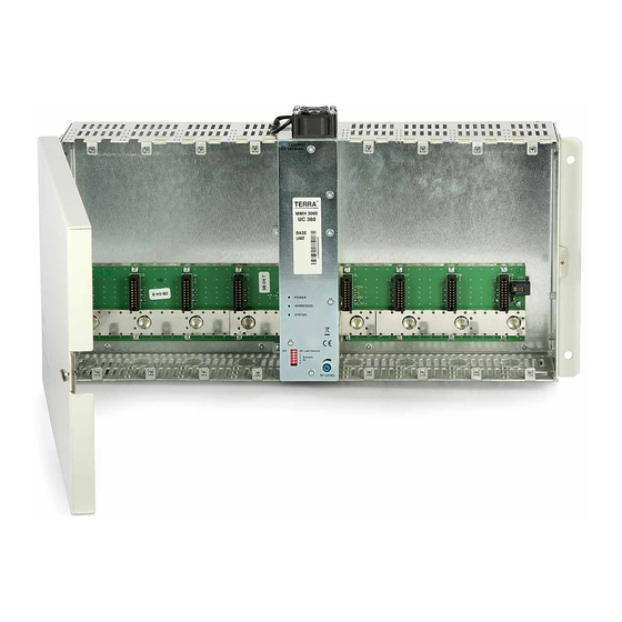
EXTERNAL VIEW The UC380 is the 19" wide and 5U height base unit. The UC380 has a built-in switch-mode power supply, RF output amplifier and connections board. It has 8 identical slots for location of the modules. TERRA ® MMH 3000 UC380 v.1... -
Page 7: Power Supply Unit Up110
Up to 16xUC380 base units can be linked together using the supplied data cables. Where more than one UC380 is connected to the data bus, it is necessary to set each base unit's identity with a virtual number. Each base unit number is set by the 5 positions DIP switch (Figure 5a, pos. 2). 4 positions (1, 2, 4, 8) are for setting of the base unit number (Figure 6). -
Page 8: Insertion/Changing Of The Module
INSERTION/CHANGING OF THE MODULE Disconnect the base unit from mains supply before insertion / changing of any module. Remove plastic covers if necessary to allow entry of any aerial or LNB feeds (Figure 5c, pos.19, page 5). The worst place by cooling conditions is position #5 (first on the right the power supply). We recommend place in to this position a module with minimal power consumption or leave empty if it is possible. -
Page 9: Connections
Flat cable 440.60 for connection of the MPEG2 TS from 1 master module to 7 slave modules is supplied with the base unit UC380. Using shears cut the flat cable carefully to the required length depending on the number of slave modules required. -
Page 10: Control And Programming
NOTE! Do not connect HANDHELD/DATA BUS ports directly of two base units! (see Figure 14). A maximum of 2 base units can be controlled by TERRA Link software and up to 16 base units by CMH Master software can be managed through a single USB port. Before connecting the PC it is necessary to ground all base units using the grounding clamps provided on the bottom side of the base unit (Figure 5b, pos. -
Page 11: Installation Example Of 3 Base Units
INSTALLATION EXAMPLE OF 3 BASE UNITS This is connection's illustration only! Do not use handheld control unit while software control from PC is in operation. LNB powering +18V from 1x rd31X in #1 position 4x rd31X (pos. #1 - #4) 4 transponders/programs from H/Hi 4 receivers are connected via through loop 1x rt31X + 3x dm31X (pos. -
Page 12: Scope Of Delivery
SCOPE OF DELIVERY 1. User manual UC380 2. Base unit UC380 - 1 pc 3. Power cord - 1 pc 4. Data bus extension cable 401.30 - 1 pc 5. MPEG2 TS distribution cable 440.60 - 1 pc 6. Load 75 Ohm - 1 pc ACCESSORIES 6. - Page 13 ÑÎÄÅÐÆÀÍÈÅ ÍÀÇÍÀ×ÅÍÈÅ ÈÇÄÅËÈЯ ------------------------------------------------------------------------------------------------ 14 ÈÍÑÒÐÓÊÖÈЯ ÏÎ ÝËÅÊÒÐÎÁÅÇÎÏÀÑÍÎÑÒÈ ------------------------------------------------------------------ 14 ÁÀÇÎÂÛÉ ÁËÎÊ UC380 -------------------------------------------------------------------------------------------------- 16 ÓÑÒÀÍÎÂÊÀ---------------------------------------------------------------------------------------------------------------- 16 ÂÅÍÒÈËЯÖÈЯ ------------------------------------------------------------------------------------------------------------ 16 ÂÍÅØÍÈÉ ÂÈÄ ---------------------------------------------------------------------------------------------------------- 17 ÈÑÒÎ×ÍÈÊ ÏÈÒÀÍÈЯ up110 ---------------------------------------------------------------------------------------- 18 ÑÎÅÄÈÍÈÒÅËÜÍÀЯ ÏËÀÒÀ ----------------------------------------------------------------------------------------- 18 ÂÛÕÎÄÍÎÉ ÓÑÈËÈÒÅËÜ Ð× --------------------------------------------------------------------------------------- 18 ÓÑÒÀÍÎÂÊÀ ÍÎÌÅÐÀ ÁÀÇÎÂÎÃÎ ÁËÎÊÀ --------------------------------------------------------------------- 18 ÓÑÒÀÍÎÂÊÀ/ÇÀÌÅÍÀ...
-
Page 14: Íàçíà×Åíèå Èçäåëèя
Коммуникация через LAN, WAN или Интернет с использованием двунаправленного TSoIP модуля, значительно расширяет возможности головной станции. Дî 8 ìîäóëåé можно âìîíòèðîâàть â áàçîâûé áëîê UC380, êîòîðûé âêëþ÷àåò áëîê ïèòàíèÿ (PSU), óñèëèòåëü Ð× è èíòåëëåêòóàëüíóþ øèíó ïåðåäà÷è äàííûõ. Øèíà ïåðåäà÷è äàííûõ àâòîìàòè÷åñêè èäåíòèôèöèðóåò... - Page 15 TERRA гарантирует, что данный продукт соответствует требованиям технических регламентов Таможенного Союза: “Электромагнитная совместимость технических средств“ ТР ТС 020/2011, “О безопасности низковольтного оборудования“ ТР ТС 004/2011. TERRA гарантирует, что данный продукт соответствует нормам безопасности по стандарту AS/NZS 60065 и нормам электромагнитной совместимости по стандартам Австралии. www.terraelectronics.com...
-
Page 16: Áàçîâûé Áëîê Uc380
â òó æå ñòîéêó, âàæíî îñòàâèòü ìèíèìàëüíîå 10-15 cm ðàññòîÿíèå ìåæäó áàçîâûìè áëîêàìè, ÷òîáû îáåñïå÷èòü íîðìàëüíûå âåíòèëÿöèîííûå óñëîâèÿ. Åñëè èñïîëüçóåòñÿ âåíòèëÿöèîííàÿ ïàíåëü 400.024 (cì. ðàçäåë ÀÊÑÅÑÑÓÀÐÛ), ñíà÷àëà ïîäêëþ÷èòå øèíó çàçåìëåíèÿ, øèíó äàííûõ è Ð× êàáåëè. Îáùèé âåñ ïîëíîñòüþ îñíàùåííîãî UC380 îêîëî 10 kg. áàçîâûé áëîê ïîñòàâëÿåòñÿ ñ... -
Page 17: Âíåøíèé Âèä
ÂÍÅØÍÈÉ ÂÈÄ UC380 - áàçîâûé áëîê øèðèíîé 19" è âûñîòîé 5U. UC380 èìååò âñòðîåííûå èñòî÷íèê ïèòàíèÿ, ñîåäèíèòåëüíóþ ïëàòó ñ öåïÿìè ðàñïðåäåëåíèÿ ïèòàíèÿ, ñèãíàëîâ óïðàâëåíèÿ è Ð× ñóììàòîðîì. Áàçîâûé áëîê èìååò 8 èäåíòè÷íûõ ñëîòîâ äëÿ óñòàíîâêè ìîäóëåé. TERRA ® MMH 3000 UC380 v.1... -
Page 18: Èñòî×Íèê Ïèòàíèя Up110
ÈÑÒÎ×ÍÈÊ ÏÈÒÀÍÈЯ up110 Èñòî÷íèê ïèòàíèÿ up110 âñòðîåí â áàçîâûé áëîê UC380 (Ðèñóíîê 5a, ïîç. 3) è ïðåäíàçíà÷åí äëÿ ïèòàíèÿ èíñòàëëèðîâàííûõ ìîäóëåé.  íîðìàëüíîì ñîñòîÿíèè èíäèêàòîð LED POWER ïîñòîÿííî ñâåòèòñÿ çåëåíûì öâåòîì. Èíäèêàòîð ADDRESSED ñâåòèòñÿ çåëåíûì öâåòîì, êîãäà ìîäóëü èñòî÷íèêà ïèòàíèÿ âûáèðàåòñÿ ïðè ïîìîùè ðó÷íîãî... -
Page 19: Óñòàíîâêà/Çàìåíà Ìîäóëя
ÓÑÒÀÍÎÂÊÀ/ÇÀÌÅÍÀ ÌÎÄÓËЯ Ïåðåä óñòàíîâêîé/çàìåíîé ëþáîãî ìîäóëÿ îòêëþ÷èòå áàçîâûé áëîê îò ïèòàþùåé ñåòè. Åñëè íåîáõîäèìî, óäàëèòå ïëàñòèêîâûå çàãëóøêè (Ðèñóíîê 5â, ïîç.19, ñòðàíèöà 15). Íàèõóäøèì ìåñòîì èç-çà óñëîâèé îõëàæäåíèÿ ÿâëÿåòñÿ ïîçèöèÿ ¹5 (ïåðâàÿ ñïðàâà îò èñòî÷íèêà ïèòàíèÿ). Ìû ðåêîìåíäóåì ïîìåñòèòü â ýòó ïîçèöèþ ìîäóëü ñ ìèíèìàëüíûì ïîòðåáëåíèåì ìîùíîñòè èëè, åñëè... -
Page 20: Ïîäêëþ×Åíèя
Ðèñóíîê 10. Ïîäêëþ÷åíèå "Master - slave" ìîäóëåé ← ðàñïðåäåëèòåëüíûé êàáåëü MPEG2 TS 440.60 Ñ áàçîâûì áëîêîì UC380 ïîñòàâëÿåòñÿ ïëîñêèé êàáåëü 440.60 äëÿ ïîäêëþ÷åíèÿ MPEG2 TS îò 1 "master" ìîäóëÿ äî 7 "slave" ìîäóëåé. Íîæíèöàìè îñòîðîæíî îáðåæüòå ïëîñêèé êàáåëü äî íåîáõîäèìîé äëèíû... -
Page 21: Óïðàâëåíèå È Ïðîãðàììèðîâàíèå
ÏÐÈÌÅ×ÀÍÈÅ! Íå ïîäêëþ÷àéòå íàïðÿìóþ ïîðòû HANDHELD/DATA BUS äâóõ áàçîâûõ áëîêîâ! (ñìîòðèòå ðèñóíîê 14). Ïðè ïîìîùè ïðîãðàììíîãî îáåñïå÷åíèÿ TERRA Link ìîæíî óïðàâëÿòü äî 2 áàçîâûõ áëîêîâ, à ïðè ïîìîùè ïðîãðàììíîãî îáåñïå÷åíèÿ CMH Master ÷åðåç îäèí ïîðò USB ìîæíî óïðàâëÿòü äî 16 áàçîâûõ... -
Page 22: Òåõíè×Åñêèå Õàðàêòåðèñòèêè
Ïîäêëþ÷åíèå èíòåðôåéñà øèíà äàííûõ/USB Âèä ñíèçó Íå ïîäêëþ÷àéòå íàïðÿìóþ ïîðòû HANDHELD/DATA BUS äâóõ áàçîâûõ áëîêîâ! èíòåðôåéñ øèíà äàííûõ/ USB UD101 èíòåðôåéñ øèíà äàííûõ/ USB UD104 USB êàáåëü ê äðóãîìó áàçîâîìó áëîêó Ðèñóíîê 13. ÒÅÕÍÈ×ÅÑÊÈÅ ÕÀÐÀÊÒÅÐÈÑÒÈÊÈ Èñòî÷íèê ïèòàíèÿ Допустимые предельные значения 180-250 V 50/60 Hz âõîäíîãî... -
Page 23: Ïðèìåð Ïðèìåíåíèя 3-Õ Áàçîâûõ Áëîêîâ
ÏÐÈÌÅÐ ÏÐÈÌÅÍÅÍÈЯ 3-Õ ÁÀÇÎÂÛÕ ÁËÎÊΠÝòî òîëüêî èëëþñòðàöèÿ ïîäêëþ÷åíèÿ! Íå èñïîëüçóéòå ðó÷íîãî ïóëüòà óïðàâëåíèÿ, ïîêà ïðîãðàììíîå óïðàâëåíèå îò ÏÊ â äåéñòâèå. Ïèòàíèå êîíâåðòåðîâ +18V îò 1x rd31X â ïîçèöèè #1 4x rd31X (ïîç. #1 - #4) 4 òðàíñïîíäåðû/ïðîãðàììû îò H/Hi 4 ïðèåìíèêè... -
Page 24: Êîìïëåêò Ïîñòàâêè
ÊÎÌÏËÅÊÒ ÏÎÑÒÀÂÊÈ 1. Èíñòðóêöèÿ ïîëüçîâàòåëÿ UC380 2. Áàçîâûé áëîê UC380 - 1 øò. 3. Øíóð ïèòàíèÿ - 1 øò. 4. Ðàñøèðèòåëüíûé êàáåëü 401.30 - 1 øò. 5. Ðàñïðåäåëèòåëüíûé êàáåëü MPEG2 TS 440.60 - 1 øò. 6. Íàãðóçêà 75 Ohm - 1 øò. - Page 25 CABECERA SEMI MODULAR MMH3000 ----------------------------------------------------------------------------------- 26 DESCRIPCIÓN DEL PRODUCTO ----------------------------------------------------------------------------------------- 26 INSTRUCCIONES DE SEGURIDAD -------------------------------------------------------------------------------------- 26 UNIDAD CENTRAL UC380 ---------------------------------------------------------------------------------------------------- 28 MONTAJE ------------------------------------------------------------------------------------------------------------------------ 28 VENTILACIÓN ------------------------------------------------------------------------------------------------------------------ 28 VISTA EXTERNA --------------------------------------------------------------------------------------------------------------- 29 ALIMENTACIÓN --------------------------------------------------------------------------------------------------------------- 30 PLACA DE CONEXIONES -------------------------------------------------------------------------------------------------- 30 AMPLIFICADOR DE SALIDA RF------------------------------------------------------------------------------------------ 30 AJUSTE DEL NÚMERO DE UNIDAD CENTRAL --------------------------------------------------------------------- 30...
-
Page 26: Cabecera Semi Modular Mmh3000
Comunicación a través de LAN, WAN o Internet a través de módulos bi-direccional TSoIP que amplían considerablemente las posibilidades de la cabecera. Hasta 8 módulos pueden ser montados en la unidad base UC380 que incorpora una fuente de alimentación, un amplificador de RF y el bus de datos inteligente. - Page 27 Unión Aduanera: “Compatibilidad electromagnética de equipos técnicos” CU TR 020/2011, “Sobre la seguridad de bajo voltaje de los equipos” CU TR 004/2011. TERRA declara que este producto es conforme a la norma de seguridad AS/NZS 60065 y las normas EMC de Australia.
-
Page 28: Unidad Central Uc380
Caso de utilizar el panel de ventilación 400.024 (ver sección accesorios) conecte primero todos los cables. Nota: el peso total de UC380 totalmente equipado es de aproximadamente 10 kg. para el montaje mural, la unidad central se dis-... -
Page 29: Vista Externa
VISTA EXTERNA La unidad UC380 tiene un ancho de 19" y ocupa una altura en rack de 5U. La unidad central incluye el módulo con fuente de alimentación y amplificación así como la placa de conexión de los módulos (8 ranuras de conex- TERRA ®... -
Page 30: Alimentación
5a, pos. 8). AMPLIFICADOR DE SALIDA RF El amplificador de salida se encarga de ajustar el nivel de salida de la UC380, tiene y puerto de test. AJUSTE DEL NÚMERO DE UNIDAD CENTRAL Usando los cables suministrados, podrá interconectar hasta 16 unidades UC380. Caso de que haya más de una UC380 conectada al bus de datos, es necesario asignar diferentes números a cada una. -
Page 31: Inserción Y Cambio Del Módulo
INSERCIÓN Y CAMBIO DEL MÓDULO Desconecte la unidad central antes de la inserción / cambio del módulo. Quite las cubiertas de plásticos si es necesario para permitir la entrada de cualquier antena o LNB (Figura 5c, pos.19, page 26). La ranura de inserción número 5 (a la derecha de la fuente de alimentación) es la que más se calienta. Intente dejar esta posición libre o usarla con módulos que consuman menor potencia. -
Page 32: Conexiones
CONEXIONES Distribución de la señal de entrada por loop through (puente) Vista superior Figura 8. Conexión del cable A/V Vista inferior Fuente A/V Corte el panel Cable A/V 400.38 Vea capítulo ACCESORIOS Figura 9. Figura 10. Conexión de módulos Master - slave ←... -
Page 33: Control Y Programación
401.30 (ver Figura 12, a). Este cable se suministra con la unidad principal. El conector para la conexión de la unidad principal al bus de datos se encuentra cerca del panel frontal de la UC380. Durante el proceso de instalación, conecte el mando programador PC100 al correspondiente puerto de entrada del panel frontal (Figura 12, No conecte el mando programador mientras esté... -
Page 34: Ejemplo De Instalación De 3 Unidades Centrales
EJEMPLO DE INSTALACIÓN DE 3 UNIDADES CENTRALES Esto son sólo ejemplos! No use el programador mientras esté usando el software de control desde su PC. Alimentación del LNB +18V desde 1x rd31X en #1 posición 4x rd31X (pos. #1 - #4) 4 transpondedores/programas desde H/Hi 4 receptores conectados vía loop through 1x rt31X + 3x dm31X (pos. -
Page 35: Contenido
CONTENIDO 1. Manual de usuario UC380 2. Unidad principal UC380 - 1 ud. 3. Cable de alimentación - 1 ud. 4. Cable bus de datos 401.30 - 1 ud. 5. Cable 440.60 de para distribución MPEG2 TS - 1 ud. -
Page 36: Diagnostic Information
DIAGNOSTIC INFORMATION / ДИАГНОСТИЧЕСКАЯ ИНФОРМАЦИЯ / INFORMATIÓN DE DIAGNÓSTICO Diagnostic messages on PC Diagnostic information on handheld Comments Аварийное сообщение на зкране ПК Диагностическая информация Комментарий на зкране пульта управления Mensajes en PC Mensajes en el programador Descripción Byte Bit Nr. 7654 3210 Diag... -
Page 37: Appendix. Tv Channels Allocation
APPENDIX TV CHANNELS ALLOCATION Standard D/OIRT Channel Frequency, Central Video carrier, Audio carrier, Channel Frequency, Central Video carrier, Audio carrier, band frequency, band frequency, 48.5-56.5 52.5 49.75 56.25 Hyper- S11 230-237 233.5 231.25 236.75 58-66 59.25 65.75 band S12 237-244 240.5 238.25 243.75... - Page 38 Standard B/Australia Standard K/OIRT, G/CCIR, I, L, H Channel Frequency, Central Video carrier, Audio carrier, Channel Frequency, Central Video carrier, Audio carrier, Audio carrier, Audio carrier, band frequency, band frequency, Standard G, H Standard I Standard K, L 470-477 473.5 471.25 476.75 470-478...
- Page 39 TERRA UAB Draugystes str. 22, LT-51256 Kaunas, Lithuania Tel.: +370 37 - 31 34 44, fax: +370 37 - 31 35 55 sales@terraelectronics.com E-mail: www.terraelectronics.com...
Need help?
Do you have a question about the UC380 and is the answer not in the manual?
Questions and answers