Table of Contents
Advertisement
Quick Links
Advertisement
Table of Contents

Related Manuals for Terra MMH3000


Summary of Contents for Terra MMH3000
- Page 1 MINI MODULAR HEADEND MMH3000 BASE UNIT UC360 User Manual English Vers. 1.01...
-
Page 2: Table Of Contents
CONTENTS MINI MODULAR HEADEND MMH3000 --------------------------------------------------------------------------------4 PRODUCT DESCRIPTION -----------------------------------------------------------------------------------------------4 SAFETY INSTRUCTIONS ------------------------------------------------------------------------------------------------4 ELECTROSTATIC DISCHARGE CAUTION --------------------------------------------------------------------------4 BASE UNIT UC360 -----------------------------------------------------------------------------------------------------------6 MOUNTING ----------------------------------------------------------------------------------------------------------------6 VENTILATION -------------------------------------------------------------------------------------------------------------6 EXTERNAL VIEW ---------------------------------------------------------------------------------------------------------7 POWER SUPPLY -----------------------------------------------------------------------------------------------------------8 CONNECTIONS BOARD -------------------------------------------------------------------------------------------------8 OUTPUT AMPLIFIER -----------------------------------------------------------------------------------------------------8 BASE UNIT NUMBER SETTING --------------------------------------------------------------------------------------8... -
Page 3: Mini Modular Headend Mmh3000
The programming of MMH3000 can be made locally by handheld control unit by connecting the USB software link using a PC or remotely through the internet or other communication line using advanced control and monitoring software. -
Page 4: Electrostatic Discharge Caution
Equipment is double insulated from the mains, with functional earthing. Functional earthing. Connect to the main potential equalization. TERRA confirms, that this product is in accordance to following norms of EU: EMC norm EN50083-2, safety norm EN60065 and RoHS norm EN50581. -
Page 5: Base Unit Uc360
BASE UNIT UC360 MOUNTING The base unit is intended to be wall mounted or fitted in a 19" rack. The base unit must be mounted vertically to allow the free flow of ventilation and allow heat to escape. The base unit must be fixed with steel screws Ø... -
Page 6: External View
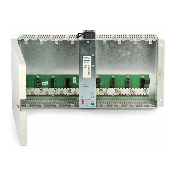
EXTERNAL VIEW The UC360 is the 5U height base unit. The UC360 has a built-in switch-mode power supply, RF output amplifier and connections board. It has 6 identical slots for location of the modules. Figure 5a. Front view Figure 5b. Bottom view - DIP switcher for setting of base unit number - Power supply and RF output amplifier section - RF LEVEL - output level regulator of the base unit... -
Page 7: Power Supply
POWER SUPPLY Power supply is integrated into the UC360 base unit and powers any combination of the installed modules. CONNECTIONS BOARD The connections board integrates the RF output of each module combiner and the DC & data distribution bus (Figure 5a, pos. 7). RF OUTPUT AMPLIFIER RF output amplifier is intended to boost, regulate output level of UC360 and has a test port. -
Page 8: Insertion/Changing Of The Module
INSERTION/CHANGING OF THE MODULE Disconnect the base unit from mains supply before insertion / changing of any module. Remove plastic covers if necessary to allow entry of any aerial or LNB feeds (Figure 5a, pos.18, page 5). Insertion module into the base unit: - put the adapters on the tuner's ports (1) - to align adapter's flat surfaces as shown in picture before inserting module (2) -
Page 9: Connections
CONNECTIONS Input signal distributing by loop through Top view Figure 8. V/A cable connection to the modulators mt310X Bottom view V/A source cut off the panel V/A cable 400.38 Figure 9. see chapter ACCESSORIES Figure 10. Master - slave modules connection ←... -
Page 10: Control And Programming
CONTROL AND PROGRAMMING HANDHELD CONTROL UNIT Maximum 2 base units could be controlled by the handheld control unit. For simultaneous control of the modules placed on two base units, it is necessary to connect handheld control unit to port HANDHELD/ DATA BUS and connect port DATA BUS with port HANDHELD/DATA BUS into another base unit by supplied cable 401.30 (Figure 12). -
Page 11: Pc Connection
NOTE! Do not connect handheld/data bus ports directly of two base units! A maximum of 2 base units can be controlled by TERRA Link software and up to 16 base units by CMH Master software can be managed through a single USB port. Before connecting the PC it is necessary to ground all base units using the grounding clamps provided on the bottom side of the base unit (Figure 5b, pos. -
Page 12: Scope Of Delivery
3. Handheld PC100 terraelectronics.com 4. USB interface UD104 Supplied together with software Terra Link 5. USB interface UD101 Supplied together with software Terra Link Accessories are not included in scope of delivery, should be ordered separately. -
Page 13: Appendix. Tv Channels Allocation
APPENDIX TV CHANNELS ALLOCATION Standard D/OIRT Channel Frequency, Central Video carrier, Audio carrier, Channel Frequency, Central Video carrier, Audio carrier, band frequency, band frequency, 48.5-56.5 52.5 49.75 56.25 Hyper- S11 230-237 233.5 231.25 236.75 58-66 59.25 65.75 band S12 237-244 240.5 238.25 243.75... - Page 14 Standard B/Australia Standard K/OIRT, G/CCIR, I, L, H Channel Frequency, Central Video carrier, Audio carrier, Channel Frequency, Central Video carrier, Audio carrier, Audio carrier, Audio carrier, band frequency, band frequency, Standard G, H Standard I Standard K, L 470-477 473.5 471.25 476.75 470-478...
- Page 15 TERRA UAB Draugystes str. 22, LT-51256 Kaunas, Lithuania Tel.: +370 37 - 31 34 44, fax: +370 37 - 31 35 55 E-mail: sales@terraelectronics.com http://www.terraelectronics.com...
Need help?
Do you have a question about the MMH3000 and is the answer not in the manual?
Questions and answers