Table of Contents
Advertisement
Quick Links
S e r v i c e L i t e r a t u r e
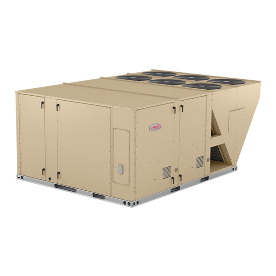
LCM036U, 048U, 060U, and 074U are ultra high efficiency
packaged units equipped with variable speed direct drive
blowers, an inverter-driven variable speed compressor,
and a variable speed outdoor fan.
Optional electric heat is factory or field installed . Electric
heat operates in single stage depending on the kW input
size. 7.5kW through 22.5 kW heat sections are available
for the LCM unit.
Information contained in this manual is intended for use
by qualified service technicians only. All specifications are
subject to change. Procedures outlined in this manual are
presented as a recommendation only and do not super-
sede or replace local or state codes.
If the unit must be lifted for service, rig unit by attaching
four cables to the holes located in the unit base rail (two
holes at each corner). Refer to the installation instructions
for the proper rigging technique.
WARNING
Improper
installation,
service or maintenance can cause property damage,
personal injury or loss of life. Installation and service
must
be performed by a licensed professional
HVAC installer or equivalent, service agency, or the
gas supplier.
WARNING
Electric shock hazard. Can cause injury
or death. Before attempting to perform
any service or maintenance, turn the
electrical power to unit OFF at disconnect
switch(es). Unit may have multiple power
supplies.
IMPORTANT
The Clean Air Act of 1990 bans the intentional
venting of refrigerant (CFC's and HCFC's) as of July
1, 1992. Approved methods of recovery, recycling
or reclaiming must be followed. Fines and/or
incarceration may be levied for non-compliance.
CAUTION
As with any mechanical equipment, contact with
sharp sheet metal edges can result in personal
injury. Take care while handling this equipment and
wear gloves and protective clothing.
UNIT INFORMATION
UNIT INFORMATION
Ultra High Efficiency LCM036U through 074U
adjustment,
alteration,
100039
02/2022
ELECTROSTATIC DISCHARGE (ESD)
Precautions and Procedures
Electrostatic
electronic components. Take precautions
to neutralize electrostatic charge by
touching your hand and tools to metal
prior to handling the control.
Table of Contents
Options / Accessories . . . . . . . . . . Page 2
Specifications . . . . . . . . . . . . . . . . . Page 5
Blower Data . . . . . . . . . . . . . . . . . . Page 6
Electrical /Electric Heat Data . . . . . Page 11
Electric Heat Capacities . . . . . . . . Page 15
Parts Arrangement . . . . . . . . . . . . Page 16
I Unit Components . . . . . . . . . . . . . Page 17
II Placement and Installation . . . . . Page 30
III Start Up Operation . . . . . . . . . . . Page 30
IV Charging . . . . . . . . . . . . . . . . . . . Page 31
V System Service Checks . . . . . . . Page 32
VI Maintenance . . . . . . . . . . . . . . . Page 32
VII Accessories . . . . . . . . . . . . . . . .Page 33
VIII Diagrams . . . . . . . . . . . . . . . . . Page 41
Page 1
LCM SERIES
3 to 6 Ton
CAUTION
discharge
can
affect
Advertisement
Table of Contents

Subscribe to Our Youtube Channel
Related Manuals for Lennox LCM Series


Summary of Contents for Lennox LCM Series
-
Page 1: Table Of Contents
LCM SERIES UNIT INFORMATION UNIT INFORMATION 3 to 6 Ton 100039 S e r v i c e L i t e r a t u r e 02/2022 Ultra High Efficiency LCM036U through 074U LCM036U, 048U, 060U, and 074U are ultra high efficiency... -
Page 2: Options / Accessories
DirectPlus™ Direct Drive ECM Blower System with VAV Factory CABINET Combination Coil/Hail Guards 13T03 Corrosion Protection (indoor coil / outdoor coil) Factory CONTROLS Commercial Controls Lennox CORE Control System - LonTalk Module 54W27 ® ® CPC Einstein Integration Factory Novar Factory ®... - Page 3 OPT IONS / A C C ESSORIES Unit Model Number Catalog Item Number ECONOMIZER High Performance Economizer With Outdoor Air Hood (Sensible Control) (Approved for California Title 24 Building Standards / AMCA Class 1A Certified) 20H48 High Performance Economizer - Includes Barometric Relief Dampers and Combination Hood Economizer Accessories 17W45...
- Page 4 OPT IONS / A C C ESSORIES Unit Model Number Catalog Item Number INDOOR AIR QUALITY Air Filters Healthy Climate High Efficiency Air Filters MERV 8 (Order 4) 54W21 ® 20 x 20 x 2 in. 52W39 MERV 13 (Order 4) MERV 16 (Order 4) 21U40 44N60...
-
Page 5: Specifications
SP ECIF IC ATIONS UN IT General Data Nominal Tonnage 3 Ton 4 Ton 5 Ton 6 Ton Efficiency Type Ultra-High Ultra-High Ultra-High Ultra-High Model Number LCM036U4E LCM048U4E LCM060U4E LCM074U4E Blower Type DirectPlus™ DirectPlus™ DirectPlus™ DirectPlus™ ECM Direct Drive ECM Direct Drive ECM Direct Drive ECM Direct Drive with SZVAV... -
Page 6: Blower Data
Page 6... - Page 7 Page 7...
- Page 8 Page 8...
- Page 9 Page 9...
- Page 10 BLOWER DATA FACTORY INSTALLED OPTIONS/FIELD INSTALLED ACCESSORY AIR RESISTANCE - in. w.g. Wet Indoor Coil Humiditrol Filters ® Electric Volume Condenser Economizer Heat 036, 048 060, 074 MERV 8 MERV 13 MERV 16 Reheat Coil 0.01 - - - - - - 0.01 0.04 0.04...
-
Page 11: Electrical /Electric Heat Data
ELECTRIC AL/ELECTRIC H EAT DATA 3 TO N Model No. LCM036U4E / LCM036U4P Voltage - 60Hz 208/230V-3ph 460V-3ph 575V-3ph Compressor Rated Load Amps Outdoor Fan Full Load Amps Motor Power Exhaust Full Load Amps (1) 0.33 HP Service Outlet 115V GFI (amps) Indoor Blower Horsepower Motor... - Page 12 ELECTRIC AL/ELECTRIC H EAT DATA 4 TO N Model No. LCM048U4E / LCM048U4P Voltage - 60Hz 208/230V-3ph 460V-3ph 575V-3ph Compressor Rated Load Amps 13.8 Outdoor Fan Full Load Amps Motor Power Exhaust Full Load Amps (1) 0.33 HP Service Outlet 115V GFI (amps) Indoor Blower Horsepower Motor...
- Page 13 ELECTRIC AL/ELECTRIC H EAT D ATA 5 TO N Model No. LCM060U4E / LCM060U4P Voltage - 60Hz 208/230V-3ph 460V-3ph 575V-3ph Compressor Rated Load Amps 14.6 Outdoor Fan Full Load Amps Motor Power Exhaust Full Load Amps (1) 0.33 HP Service Outlet 115V GFI (amps) Indoor Blower Horsepower Motor...
- Page 14 ELECTR IC AL/ELECTRIC HEAT D ATA 6 TO N Model No. LCM074U4E / LCM074U4P Voltage - 60Hz 208/230V-3ph 460V-3ph 575V-3ph Compressor Rated Load Amps 16.9 Outdoor Fan Full Load Amps Motor Power Exhaust Full Load Amps (1) 0.33 HP Service Outlet 115V GFI (amps) Indoor Blower Horsepower Motor...
-
Page 15: Electric Heat Capacities
ELECTRIC H EAT CAPACITIES 7.5 kW 15 kW 22.5 kW Input No of Btuh No of Btuh No of Btuh Voltage kW input kW input kW input Stages Output Stages Output Stages Output 19,200 11.2 38,200 16.9 57,700 21,500 12.6 43,000 18.9 64,500... -
Page 16: Parts Arrangement
LCM PARTS ARRANGEMENT REHEAT COIL BLOWER EVAPORATOR (OPTIONAL) (DIRECT DRIVE) COIL CONDENSER FILTERS (4) 20 X 20 X 2” COIL GUARDS (OPTONAL ECONOMIZER (OPTIONAL) 8.8.8.8 CONDENSER COIL CONDENSATE DRAIN ELECTRIC HEAT (Optional) UNIT COMPRESSOR CONTROLLER FIGURE 1 LCM CONTROL BOX K191 FIGURE 2 Page 16... -
Page 17: I Unit Components
CORE Unit Controller (A55) Wireless Control (W4) J384 J385 J386 J387 J388 J389 J390 J391 J392 J393 J394 J383 J395 J382 J381 J358 P2 Expansion 4−Character Seven Segment LED Card Connection White Push (C4) Button J380 MODBUS J413 Black Push 24VAC 24VAC J379... - Page 18 B-Cooling Components Attention! All units use a single cooling circuit consisting of a variable Use this QR code to download the mobile speed compressor, fin/tube condenser coil and evapora- service app. Follow the prompts to pair the tor coil. See figure 5. All units use one draw-through type condenser fan and a single direct drive blower.
- Page 19 PLUMBING AND COMPRESSOR PROTECTION COMPONENTS CONDENSER COIL EVAPORATOR COIL EXPANSION DRIER VALVE INDOOR BLOWER SECTION RETURN AIR SECTION HEAT SECTION COMPRESSOR FIGURE 5 4-Thermistors Each thermistor must be specifically placed for proper unit operation and to initiate valid alarms. See table 1 for prop- Units are equipped with four factory-installed thermistors er locations.
- Page 20 THERMISTOR LOCATION RT42 & 46 036 & 048 THREE-ROW EVAPORATOR COIL (VIEW FROM FRONT SIDE OF UNIT) RT46 CLAMP THERMISTOR TO BARE COPPER; TOR SLEEVE TOR TUBE DETAILS NOT TO SCALE TXV BULB RT42 SUCTION LINE FIGURE 6 Page 20...
- Page 21 THERMISTOR LOCATION RT42 & 46 060U & 074 FOUR-ROW EVAPORATOR COIL (VIEW FROM FRONT SIDE OF UNIT) RT46 CLAMP THERMISTOR TO BARE COPPER; NOT THE DISTRIBUTOR SLEEVE DISTRIBUTOR TUBE DETAILS NOT TO SCALE TXV BULB RT42 SUCTION LINE FIGURE 7 Page 21...
- Page 22 WARNING THERMISTOR LOCATION RT44 & RT48 036-048 CONDENSER COIL Electrical shock hazard. Compressor must be (VIEW FROM FRONT SIDE OF UNIT) grounded. Do not operate without protective cover RT48 over terminals. Disconnect power before removing protective cover. Discharge capacitors before servicing unit.
- Page 23 COMPRESSOR DIAGNOSTICS Motor Winding Resistance at 77°F (+/-7%) Unit Size 0.64 0.63 0.63 0.70 0.70 0.70 060/074 0.62 0.62 0.62 FIGURE 10 Page 23...
- Page 24 6-Compressor Inverter A192 a MODBUS protocol. Inverter status and diagnostics are continuously monitored and reported to the Unit Controller WARNING such as: -Improper Unit Controller input voltage compared to unit Electrical Hazard model number High Voltage -High input voltage Wait 7 Minutes -Low input voltage Electrical components may hold charge.
- Page 25 TABLE 2 INVERTER-RELATED ALARMS ALARM DISPLAY MESSAGE EVENT ACTION CODE Possible alarming values for Prodigy Alarm 187 are: 12 - High compressor input current 13 - High heat sink temperature 14 - High PFC input current Alarm might be caused by outdoor fan abnormal operation, high ambient conditions, dirty outdoor coil, INVERTER LOW LEVEL refrigerant overcharge, or a blocked heat sink.
- Page 26 INVERTER WIRE ROUTING TRANSFORMER A192 INVERTER 208/230V INVERTER BOARD SHOWN FILTER BOARD W V U High voltage enters the filter board here. High voltage enters the compressor here. COMPRESSOR REACTOR FIGURE 12 C-Blower Compartment INVERTER HEAT SINK Units are equipped with a variable speed, direct drive TOP VIEW blower.
- Page 27 A-Blower Operation B-Determining Unit CFM Refer to the Unit Controller Setup Guide to energize blow- CFM is calculated using a supplied pressure transducer er. Use the mobile service app menu; see SERVICE > and can be viewed in the mobile service app. CFM can also be manually checked as follows: TEST.
- Page 28 C-Adjusting Unit CFM Blower calibration is required only on units that are newly installed or if there is a change in the duct work or air filters The supply CFM can be adjusted by changing Unit Con- after installation. Use the mobile service app to navigate troller settings.
- Page 29 D-ELECTRIC HEAT COMPONENTS ELECTRIC HEAT COMPONENTS Electric heat match-ups are found in the ELECTRICAL DATA tables. See table of contents. All electric heat sec- tions consist of electric heating elements exposed directly to the air stream. See figure 16. See figure 17 for vestibule parts arrangement.
-
Page 30: Placement And Installation
6-Heating Elements HE1 through HE6 II-PLACEMENT AND INSTALLATION Heating elements are composed of helix wound bare Make sure the unit is installed in accordance with the in- nichrome wire exposed directly to the air stream. Three stallation instructions and all applicable codes. See ac- elements are connected in a three-phase arrangement. -
Page 31: Charging
B-Cooling Start up 4 - Compare the normal operating pressures to the pressures obtained from the gauges. Minor 1 - Initiate full load cooling operation using the following variations in these pressures may be expected due mobile service app menu path: to differences in installations. -
Page 32: System Service Checks
V- SYSTEMS SERVICE CHECKS TABLE 7 581010-01 A-Cooling System Service Checks LG/LC 048U NORMAL OPERATING PRESSURES LCM units are factory charged and require no further ad- Outdoor Coil Discharge Suction + 5 justment; however, charge should be checked periodically Entering Air Temp +10 psig psig using the approach method. -
Page 33: Accessories
CLEAN CONDENSER COIL ENDPLATE IS SECURED Remove unit top panel and condenser section access TO MULLION TOP VIEW panel. Remove screws securing coil end plate to mullion. Remove wire ties connecting coils slabs and separate slabs 3-4” (76-102mm). SUPPLY Clean coils with detergent or commercial coil cleaner. Rinse thoroughly with water and reassemble field-provided wire ties to connect coil slabs. - Page 34 MANUAL OUTDOOR AIR DAMPER ASSEMBLED ROOF MOUNTING FRAME SLIDE DAMPERS TO ADJUST FRESH AIR INTAKE FIGURE 20 FIGURE 22 TYPICAL FLASHING DETAIL MOTORIZED OUTDOOR AIR DAMPER UNIT BASE BOTTOM UNIT BASE RAIL FIBERGLASS INSULATION (Furnished) COUNTER FLASHING (Field Supplied) NAILER STRIP (Furnished) CANT STRIP (Field Supplied)
- Page 35 D-Supply and Return Diffusers Note - Network OAS signal and California Title 24 Com- pliance options use either TEMPERATURE OFFSET or Optional flush mount diffuser/return FD9-65 and FD11-95 TEMPERATURE SETPT mode. and extended mount diffuser/return RTD9-65 and RTD11- Minimum Position 95 are available for use with all LGM units.
- Page 36 SENSOR LOCATION RT17 OUTDOOR AIR SENSOR (SECURED TO INSIDE OF CORNER MULLION) RT16 RETURN AIR SENSOR DISCHARGE AIR SENSOR FIGURE 25 F-Power Exhaust Relay K65 (power exhaust units) HORIZONTAL AIRFLOW Power exhaust relay K65 is a DPDT relay with a 24VAC DUCT coil.
- Page 37 TABLE 11 ECONOMIZER MODES AND SETPOINT Free| Free Field- Dampers will modulate to 55°F discharge air (RT6) when Permitted Cooling Cooling Provide outdoor air is suitable: Inputs Mode Setpoint Sensors Outdoor air temperature (RT17) is less than return air tem- TEMP OFFSET None Needed...
- Page 38 I-Needlepoint Bipolar Ionizer (Optional) REMOVE IONIZER The optional, brush-type ionizer produces positive and RETAIN THE SCREW TO SECURE THE negative ions to clean air and reduce airborne contami- BACK SIDE OF THE IONIZER BRACKET nants. The ionizer was designed to be low maintenance. The device should be checked semi-annually to confirm REMOVE THE TOP RIGHT SCREW SECURING THE BACK OF THE...
- Page 39 J-Hot Gas Reheat Default Reheat Operation Hot gas reheat units provide a dehumidifying mode of op- During reheat mode free cooling is locked out. eration. These units contain a reheat coil adjacent to and A-Thermostat Mode With 24V Humidistat downstream of the evaporator coil. Reheat coil solenoid valve, L14, routes hot discharge gas from the compressor No Y1 demand but a call for dehumidification: to the reheat coil.
- Page 40 REHEAT MODE REFRIGERANT ROUTING RETURN OUTDOOR EVAPORATOR EXPANSION COIL VALVE REHEAT COIL SUPPLY COMPRESSOR CONDENSER COIL CHECK VALVE REHEAT VALVE FIGURE 30 COOLING MODE REFRIGERANT ROUTING RETURN OUTDOOR EVAPORATOR EXPANSION COIL VALVE REHEAT COIL SUPPLY COMPRESSOR CONDENSER COIL CHECK VALVE REHEAT VALVE FIGURE 31...
-
Page 41: Diagrams
VIII-Wiring Diagrams and Sequence of Operation LGM/LCM036/074 J Voltage TO A3 ON SHIELDED GAS UNITS. CABLE REF A−SECT LOC CC01−02 RED−BLK 24VAC RT17 SHIELDED HPSW1 CABLE RED−BLK RED−BLK 24VAC RT48 HTSW1 24VAC RED−BLK 5VDC RT46 LPSW1 RED−BLK RT42 RED−BLK RT44 MAIN CTRL J389 J390... - Page 42 LGM/LCM036/074 G Voltage TO A3 ON SHIELDED GAS UNITS. CABLE REF A−SECT LOC CC01−02 RED−BLK 24VAC RT17 SHIELDED HPSW1 CABLE RED−BLK RED−BLK 24VAC RT48 HTSW1 24VAC RED−BLK 5VDC RT46 LPSW1 RED−BLK RT42 RED−BLK RT44 MAIN CTRL J394 J378 J390 J390 J389 J390 J392...
- Page 43 LGM/LCM036/074 Y Voltage SHIELDED TO A3 ON CABLE GAS UNITS. REF A−SECT RED−BLK LOC CC01−02 24VAC RT17 SHIELDED HPSW1 CABLE RED−BLK RED−BLK 24VAC HTSW1 RT48 ODF1 24VAC RED−BLK RT46 LPSW1 RT42 RED−BLK RED−BLK RT44 MAIN CTRL J389 J390 J392 J395 J394 J378 J390...
- Page 44 Cooling Sequence of Operation Power: 1 - Line voltage energizes transformer T1. T1 provides 24VAC power to the A55 Unit Controller. A55 provides 24VAC to the unit cooling, heating and blower controls. 2 - Line voltage provides voltage to compressor crankcase heater relay K191-1 N.C. contacts, compressor contactor K1, blower motor B3, and outdoor fan motor B4 (on G volt units line voltage is supplied to two fuses F27, transformer T4, blower motor B3, and outdoor fan motor B4).
- Page 45 E1EH 7.5, 15, 22.5 - G, J VOLT Page 45...
- Page 46 E1EH 7.5, 15, 22.5 - G, J VOLT WITH SCR Page 46...
- Page 47 E1EH 7.5, 15, 22.5 - Y VOLTAGE Page 47...
- Page 48 E1EH 7.5, 15, 22.5 - Y VOLTAGE WITH SCR Page 48...
- Page 49 Sequence of Operation -E1EH 7.5, 15, 22.5 - G, J Voltage HEATING ELEMENTS: 4 - 7.5kW, 15kW units - N.O. contacts K15-1 close ener- gizing HE1. 1 - Terminal Strip TB2 is energized when the unit 22.5kW units - N.O. contacts K15-1 close energizing disconnect closes.
- Page 50 ELECTRONIC OR ELECTROMECHANICAL THERMOSTAT A173 CTRL SMOKE DETECT J250 P250 P251 J251 J252 P252 P253 J253 FIRE ALARM CONTACT SUPPLIED BY OTHERS FROM IAQ WIRING DIAGRAM DI−1 P299 P387 J299 J387 MAIN CTRL J297 J298 P297 P298 J387 J298 J297 J299 IAQ+ IAQ+ BACNET GATEWAY...
- Page 51 ECONOMIZER MS7110K RANGE 2−10 VDC NF24−SR AF24−SR RANGE 2−10 VDC P104 P105 RT16 J104 J105 P384 J384 MAIN CTRL Model: LCM, LGM Series RTU HTG CLG ACCS ACCS Economizer & Motorized OAD WIRING DIAGRAM FLOW Voltage: All Voltages 538072−01 Supersedes: N/A Form No: Rev:0 Page 51...
Need help?
Do you have a question about the LCM Series and is the answer not in the manual?
Questions and answers