Advertisement
Quick Links
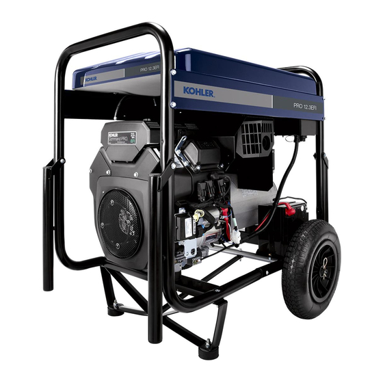
PRO 12.3 EFI
Generator Service Manual
IMPORTANT:
Read all safety precautions and instructions carefully before operating equipment.
Ensure equipment is stopped and level before performing any maintenance or service.
For all engine related maintenance, disassembly and reassembly, refer to service manual of engine
powering this equipment.
2
Safety
3
Specifications
6
Troubleshooting
9
Electrical System
17
Disassembly/Inspection and Service
22
Reassembly
34 690 01 8/16a
KohlerPower.com
1
Advertisement

Related Manuals for Kohler PRO 12.3 EFI


Summary of Contents for Kohler PRO 12.3 EFI
- Page 1 PRO 12.3 EFI Generator Service Manual IMPORTANT: Read all safety precautions and instructions carefully before operating equipment. Ensure equipment is stopped and level before performing any maintenance or service. For all engine related maintenance, disassembly and reassembly, refer to service manual of engine powering this equipment.
-
Page 2: Safety Precautions
Safety SAFETY PRECAUTIONS DANGER: A hazard that will result in death, serious injury, or substantial property damage. WARNING: A hazard that could result in death, serious injury, or substantial property damage. CAUTION: A hazard that could result in minor personal injury or property damage. NOTE: is used to notify people of important installation, operation, or maintenance information. -
Page 3: Identification Numbers
Specification IDENTIFICATION NUMBERS Kohler identification numbers (model, specification and serial) should be referenced for efficient repair, ordering correct parts, and engine replacement. Model ..... - Page 4 Specification TORQUE SPECIFICATIONS PRO 12.3 EFI Control Panel Fastener 9.0 N·m (79 in. lb.) Engine Mount 9.9 N·m (87 in. lb.) Fastener Front Cover 21.0 N·m (186 in. lb.) Fastener Fuel Tank 9.0 N·m (79 in. lb.) Fastener Muffler Shield to Exhaust Studs 27.8 N·m (246 in.
-
Page 5: General Torque Values
Specification GENERAL TORQUE VALUES English Fastener Torque Recommendations for Standard Applications Bolts, Screws, Nuts and Fasteners Assembled Into Cast Iron or Steel Grade 2 or 5 Fasteners Into Aluminum Size Grade 2 Grade 5 Grade 8 Tightening Torque: N·m (in. lb.) ± 20% 8-32 2.3 (20) 2.8 (25) -
Page 6: Troubleshooting Guide
Troubleshooting TROUBLESHOOTING GUIDE When troubles occur, be sure to check simple causes which, at first, may seem too obvious to be considered. For example, a starting problem could be caused by an empty fuel tank. Some general common causes of generator troubles are listed below. Use these to locate causing factors. Condition Possible Cause Solution... - Page 7 Troubleshooting No or Low Output Voltage Alternator Specification 1. Engine speed set too low. Needs to be set for 3600 Unit Ohms RPM at no load. Adjust if necessary. If speed is correct proceed to next step. Stator Winding 0.077 2.
- Page 8 Troubleshooting 5. Isolate all main stator leads and measure resistance 1. Cut wire on 1 side of each diode from rotor. across each winding and check each main stator 2. Use a meter set to diode test and check each lead to ground.
-
Page 9: Electrical System
Electrical System 0317-09 TEMP AIR ADMISSION TEMP HUILE OIL TEMP CAPTEUR VITESSE AJUSTAGE VITESSE CAPT PRESSION AIR CAPTEUR OXYGENE KILL 0318-13 STOP INITIALISATION 0318-09 0320-07 0320-16 34 690 01 8/16 KohlerPower.com... - Page 10 Electrical System V/J8 V/J7 V/J6 V/J5 V/J4 LINE V/J2 LINE LINE VJ/1 LINE 0315-14 0315-13 KohlerPower.com 34 690 01 8/16...
- Page 11 Electrical System 34 690 01 8/16 KohlerPower.com...
- Page 12 Electrical System 0320L19 0524 DIAG DIAGNOSTIQUE 0319-01 DEFAUT MOTEUR FUEL PUMP POMPE FUEL 0320L11 INJECTEUR B 0320L10 INJ A INJECTEUR A COIL B D'ALLUMAGE B BOBINE COIL A D'ALLUMAGE A 0320L07 BOBINE BATT + BATTERIE 0318-17 KohlerPower.com 34 690 01 8/16...
- Page 13 Electrical System PRO 12.3 EFI Alternator Output Wiring Diagram BOBINAGE AUXILIAIRE AUXILIARY WINDING ALTERNATEUR GENERATOR 0317-17 0315T18 0317-17 6mm² SILICABLE CSP Classe 5 - Bleu 10mm² 0317-13 0317-12 0315Q18 10mm² Alternator 12V Output Idle Module MODYS Control Panel 34 690 01 8/16...
- Page 14 Electrical System 0315-17 CURRENT MEASURE MESURE COURANT 0315-17 0317-02 SUPPLY ALIMENTATION 0318-04 080B 0315-17 FREQUENCY FREQUENCE DETECTION 0315-17 DEFAUT 0319-20 PRESSION HUILE OIL PRESSURE SHUTDOWN ORDRE EXTERIEUR EXTERNAL ORDER + BATTERIE + BATTERY - BATTERIE - BATTERY KohlerPower.com 34 690 01 8/16...
- Page 15 Electrical System 0317-14 0317-14 0320-02 0320-19 0524 COMMANDE RALENTI IDLE CONTROL 080A 0319-06 080B 0319-05 0318-03 COMMANDE DEMARREUR STARTER CONTROL 0317-16 0318-08 COMMANDE ELECTROVANNE FUEL SOLENOID CONTROL 34 690 01 8/16 KohlerPower.com...
- Page 16 Electrical System WARNING Before working on engine or equipment, disable engine as Accidental Starts can cause severe injury or follows: 1) Disconnect spark plug lead(s). 2) Disconnect death. negative (–) battery cable from battery. Disconnect and ground spark plug lead(s) Do not allow children to operate generator.
- Page 17 Disassembly/Inspection and Service PRO 12.3 EFI Components Fuel Tank Cap Fuel Filter Fuel Valve Fuel Tank Support Muffler Shield Battery Battery Bracket Carbon Filter Pipe Union Alternator Box Cover Alternator Box Control Panel Carbon Canister Carbon Canister Oxygen Sensor Alternator Shield...
- Page 18 Disassembly/Inspection and Service WARNING Before working on engine or equipment, disable engine as Accidental Starts can cause severe injury or follows: 1) Disconnect spark plug lead(s). 2) Disconnect death. negative (–) battery cable from battery. Disconnect and ground spark plug lead(s) Do not allow children to operate generator.
- Page 19 Disassembly/Inspection and Service Remove Muffler Shiel PRO 12.3 EFI Control Panel & Side Rails NOTE: Muffler shield can be removed as an assembly. Disassembly of muffler shield is not necessary unless a part is cracked or bent. 1. Disconnect wire connector to engine from oxygen sensor.
- Page 20 Disassembly/Inspection and Service PRO 12.3 EFI Engine and Alternator Frame Engine Alternator Mount Engine Mount Remove Engine and Alternator At this point engine and alternator can be removed as a unit to further disassemble or alternator can be removed from engine for disassembly. To remove engine and alternator as a unit, follow next few steps, otherwise continue to Remove Stator &...
- Page 21 Disassembly/Inspection and Service PRO 12.3 EFI Alternator End Cover Frame Stator Front Cover Front Cover Shield Alternator Box Wiring Board Rotor Bearing Through Bolt Capacitor Rubber Cap Remove Stator & Frame Remove Rotor NOTE: Take care not to damage stator coil and rotor 1.
- Page 22 Reassembly PRO 12.3 EFI Alternator End Cover Frame Stator Front Cover Front Cover Shield Alternator Box Wiring Board Rotor Bearing Through Bolt Capacitor Rubber Cap 2. Gently guide rotor into stator, aligning bearing with Install Front Cover (if required) bearing recess in back side of frame.
- Page 23 Alternator Mount Engine Mount Install Engine and Alternator (if required) PRO 12.3 EFI Control Panel & Side Rails If engine and alternator were removed as a unit in disassembly, install engine and alternator. 1. Lower engine and alternator, positioning engine mounts and alternator mount.
- Page 24 Reassembly PRO 12.3 EFI Components Fuel Tank Cap Fuel Filter Fuel Valve Fuel Tank Support Muffler Shield Battery Battery Bracket Carbon Filter Pipe Union Alternator Box Cover Alternator Box Control Panel Carbon Canister Carbon Canister Oxygen Sensor Alternator Shield Strap...
- Page 25 Reassembly Install Side Rails and Control Panel PRO 12.3 EFI Fuel Tank NOTE: A clamping device or an assistant to hold assembly while installing will make process easier. Secure side rails and control panel to frame with screws. Torque to 9.0 N·m (79 in. lb.).
- Page 26 Reassembly Connect Alternator Wires CAUTION Electrical Shock can cause injury. Do not touch wires while engine is running. Never operate generator in rain or snow. Never touch generator with wet hands or electrical shock may occur. 1. Remove alternator box cover. 2.
- Page 27 34 690 01 8/16 KohlerPower.com...
- Page 28 © 2014, 2016 by Kohler Co. All rights reserved. KohlerPower.com 34 690 01 8/16a...
Need help?
Do you have a question about the PRO 12.3 EFI and is the answer not in the manual?
Questions and answers