
Related Manuals for Aston Global ZA219-R


Summary of Contents for Aston Global ZA219-R
- Page 1 INSTALLATION AND OWNER'S MANUAL Steam Bath Model Number: ZA219-R Please carefully read these instructions before you begin to install the products. 07/11 Rev A P/N:100053-0 8...
-
Page 2: Before You Start
Before you start Thank you for purchasing your Aston steam shower. We hope that it will provide you with years of satisfying use and enjoyment. This instruction manual explains the benefits of using a steam shower and provides installation, operation, and care instructions for your new Aston steam shower. -
Page 3: Important Safety Instruction
Important Safety Instruction WARNING: To reduce the risk of drowning, electrical shock, or injury, read the following important precautions before using the unit. If you do not fully understand the meaning of any of the precautions and warnings please consult your dealer or the manufacturer for a full explanation. - Page 4 THE FOLLOWING WARNING ONLY APPLY TO UNITS THAT ARE A COMBINATION STEAM SHOWERS/STEAM BATH UNIT CONTAINING AN ATTACHED HYDRO-MASSAGE BATHTUB 1. WARNING: To avoid the risk of accidental injury or drowning children should not use the hydro massage bathtub without adult supervision. 2.
-
Page 5: Terms And Definitions
Terms and Definitions Becoming familiar with commonly used plumbing and electrical terms will help you as you use this owner's manual and when you consult the dealer regarding parts and service. Amperes Commonly called Amps, rating for flow of electricity American Wire Gauge (see Wire Gauge), sizing standard for wire diameter Circuit... - Page 6 NEC (National Electric Code) (USA) Universal set of standards governing proper electrical installation Neutral When measure using a multi-meter will measure 0 to earth ground NFPA (National Fire Protection Association) (USA) Develops national safety standards for fire protection related to all types of material Owner's Manual Booklet supplied with each unit containing information about installation, operation, and care of the unit...
- Page 7 Line (L1) = 110-120 VAC (Black or “Hot 1”) Line (L2) = 110-120 VAC (Red or White or “Hot 2”) Ground (G) = (Green or Bare wire) 230 @50Hz VAC (International) Most common residential voltage in Europe and other countries outside of the US and Canada. VAC is delivered to customers using three conductors with the following color code and voltage: Line (L) = 230 VAC (Brown)
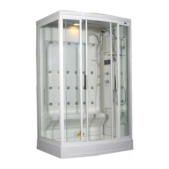
- Page 8 FEATURES 1.Rainfall Shower head 8.Mirror 9.Drain 2.Speaker 10.Light 3.Handheld Shower Wand 11.Exhaust Fan 4.Control Keypad Panel 12.Body Jets 5.Diverter Valve 6.Thermostatic Faucet 13.Steam Outlet 7.Door Handles 14.Steam Unit Drain Port...
-
Page 9: Supplied Hardware
SUPPLIED HARDWARE M5x30 SCREW PACK (1) SCREW PACK (2) M5x25 M4x30 SCREW PACK (3) M4x50 M4x60 M4x16 SCREW PACK (4) M5x60 M4x30 SCREW PACK (5) M4x35 M4x30 SCREW PACK (6) M5x25 SUPPLIED PARTS... - Page 10 Installation Guide Please read and follow the installation instructions and guidelines in this section. Failure to follow the recommended instructions and installation techniques may lead to possible damage to the unit or the surrounding area and can affect warranty claims. ATTENTION: This unit requires assembly.
- Page 11 7. CAUTION: The flexible drain should have a level or slight grade to allow free and easy flow to the floor drain. Failure to do so can cause possible leaks and flooding. 8. WARNING: It is recommended that the exhaust fan provided with the unit be vented to the outside to provide proper steam ventilation after use.
- Page 12 Electrical Requirements Unit must be connected by a licensed electrician for your state to a GFCI protected circuit in order for the warranty to be valid. Installation by a Licensed Electrician Electrical: 30A @ 120 VAC Must be connected to a GFCI protected circuit.
-
Page 13: Installation
Installation Install your unit according to the directions in this section in the order presented. Step 1 Install the drain Locate the accessory and manual box and remove the individual screw and hardware packages and lay them out in sequential order to aid in completing the rest of the installation. - Page 14 Step 2 Level the base for proper drainage The base unit is constructed with several leveling feet. Each foot has a locking nut. Use an adjustable wrench and level to complete this next step. 1. Loosen all of the locking nuts so that the leveling feet are free and easy to move.
- Page 15 Step 3 Install the flexible drain hose DRAIN ASSEMBLY Decorative drain cover (OPTIONAL) Upper drain body Drain compression nut Gasket Lower drain body Flex drain hose Drain hose gasket Please see the drain kit diagram provided. 1. Place the compression nut onto the flex hose. 2.
- Page 16 Step 4 Assemble the glass panel SCREW PACK 1. Remove and inspect all of the glass panels. If any are broken, please contact your dealer or the manufacturer. NOTE: The glass panels are labeled to indicate the direction for the top of the glass panels.
- Page 17 4. Apply a liberal bead of sealant on the bottom rail from the slot that receives the glass panel out to the end of the rail. NOTE: The next steps of assembly will require two people. 5. Choose the left side glass panel and insert it into the left slot on the bottom rail.
- Page 18 1. Insert the aluminum channel on to the glass door panel based on the hand of the unit. NOTE: No silicone is needed at this time after final assembly of the unit you will come back and apply silicone to this join 2.
- Page 19 Step 5 Assemble the acrylic back and side panel(s) SCREW PACK 1. Open and remove the acrylic back and side panel(s) and inspect for damage. IMPORTANT: Please note the direction of the screw head. Make sure you can get a screwdriver or drill bit on each screw head. Depending on your unit, you may need to use screwdrivers or drill bits of various sizes to gain proper access to each screw head.
- Page 20 additional holes. Be sure to pilot drill the new hole location first before moving to a larger bit. Failure to use a pilot drill can cause the acrylic to crack or chip. Fill any unused hole with sealant. 3. Using a caulk gun with appropriate bathroom caulk place the tip of the caulk gun into the opening between the two panels.
- Page 21 Step 6 Install the acrylic wall assembly on the base SCREW PACK NOTE: The acrylic wall assembly can be heavy so please use caution when lifting it and placing it onto the base. 1. Lift and place the acrylic wall assembly onto the base to dry fit and check for proper hole alignment.
- Page 22 Step 7 Install the glass panel assembly on to the base SCREW PACK NOTE: As with the acrylic assembly, the glass panel assembly is heavy to lift. Please use caution when lifting this assembly and use two people to lift it into place.
- Page 23 6. Place the glass panel assembly back onto the base assembly aligning the holes. 7. Using Screw Pack 4 lightly screw the acrylic panels into the aluminum frame of the glass panel assembly. 8. You will find a separate Screw Pack 4 with a single screw and decorative cap.
- Page 24 Step 8 Install the ceiling panel SCREW PACK NOTE: The ceiling panel is large and can be an odd shape. Please use caution when lifting this assembly and use two people to lift it into place. 1. Lift the ceiling into place onto the glass and acrylic walls. 2.
- Page 25 Step 9 Final assembly and sealing After you have installed and lightly assembled the cabinet walls, you can begin to fully secure all screws and bolts. Tighten the screws in the following order: 1. Acrylic wall to acrylic wall joint a.
- Page 26 Step 10 Install the decorative trim panels (depending on the unit) SCREW PACK If your unit includes a decorative trim panel, use the following steps to install the trim piece. 1. Using Screw Pack 6 use the M4 X 30mm screws, nuts, and washers to bolt the trim piece into the ceiling panel 2.
- Page 27 Step 11 Install glass sliding doors 1. Remove and inspect the glass doors. If any are damaged or broken, please contact your dealer or the manufacturer. 2. Determine which door is the right door and which is the left by locating the two holes used for the door handles.
- Page 28 tube and back plastic washer on the door roller. 5. Taking one of the doors, with the two holes for the door handles located so that they are in the center of the door opening, slide the door over the top two-door roller mounts.
- Page 29 Step 12 Install the door handles 1. The door handles are located within the accessory manual box. Remove them from the packaging and note the end with the knob on it. The door knob will be located to the top after final installation. 2.
- Page 30 Step 13 Install the adjustable shower wand holder The mounting screws to mount the shower wand holder should already be in place on the acrylic panel assembly. Remove them for this assembly. 1. Assemble the soap dish and the shower wand holder on the slide bar. Note the direction of the soap dish holder relative to the shower wand holder.
- Page 31 Step 14 Install the shower wand and hose 1. The shower wand hose has two tapered ends. One end has an O-ring around the outside. This o-ring indicates the end of the hose with the vacuum break diaphragm, used to prevent potential back flow and contamination of the drinking water.
- Page 32 Step 15 Install the mirror 1. Unpack the mirror and inspect for damage. If it is broken or damaged, please contact your dealer or the manufacturer. 2. Based on your model the mirror may or may not have an orientation. Please note this when installing the mirror.
-
Page 33: Step 17 Plumbing Connections
Step 16 Install the overhead showerhead 1. Remove the showerhead from the packaging. 2. Install the showerhead onto the showerhead spout located in the center of the unit's ceiling. If the spout is loose, tighten it with the locking nut located on the top of the ceiling. -
Page 34: Step 19 Supply Connections
Step 18 Install the showerhead hose 1. Insert the showerhead hose into one of the access holes located in the ceiling of the unit. 2. Install the elbow/barb fitting provided onto the showerhead spout and orient the fitting so that it is in line with the showerhead hose. 3. -
Page 35: Step 20 Electrical Connections
Step 20 Electrical connections WARNING: Any final electrical connections must be to a GFCI protected circuit and made by a certified electrician. Based on your unit you may or may not have to connect the main control box to the electrical disconnect terminals. If you need to connect the main control box to the electrical disconnect terminals, then insert the connection wire into the disconnect terminal provided a ground (G), Line (L), and neutral (N) terminals are provided. - Page 36 Test the system prior to final installation After completion of the electrical and plumbing connections, we recommend that you conduct a system test to ensure all connections are working properly before placing the unit into its final location. Follow these steps to test the system: With the drain installed, turn on the supply lines, check for leaks, and repair if necessary.
-
Page 37: Operation
Operation Before operating this unit ensure you have read and understand all of the warnings and safety statements in this manual. You can review them now on page . If you do not understand any of these warnings or statements, please contact your dealer or the manufacturer for an explanation. - Page 38 Over head shower Body & Neck massage jets Handheld shower Hot water Cold water Steam generator Note: This diagram is for reference purpose only, and the actual connections may vary.
- Page 39 Components Diverter valve The diverter valve is used to control the flow of water to the following devices: The overhead shower The body jets The shower wand To operate the diverter valve, rotate to the device you wish to use. Return the device to the “off”...
- Page 40 4. Press the main “on/off” button to turn on the power. 5. Rotate the diverter valve to the overhead shower position. 6. Press the “shower” button on the control panel. 7. Water will begin to flow from the showerhead. 8. Set the thermostatic valve. 9.
- Page 41 Functions Body jets Based on the typical residential water pressure and flow rates not all of the body jets can work at the same time. Because of this issue, the body jets are broken down into separate zones. Based on the model, your unit will have either three or four zones.
- Page 42 b. Press the shower button to operate the neck jets. c. Press the same local button to turn off the zone. Auto Cycle Mode - You can auto cycle through three zones of body jets. In this mode, each zone will turn on for approximately 10 seconds and then cycle to the next zone for 10 seconds.
- Page 43 E. Unconsciousness and danger of drowning To operate the steam generator use the following instructions: 1. Press the main “on/off” button to turn on the power. 2. Press the “steam” button to start the steam generator. Once you start the steam generator, it will automatically fill with water and will produce steam within three (3) to five (5) minutes.
-
Page 44: Exhaust Fan
Light 1. Press the main “on/off” button to turn on the power. 2. Press the “light” button to turn the light on. 3. Press the “light” button again to turn the light off. Optional LED light - Some units have an optional LED light installed. To change the functions of the LED light press the “light”... -
Page 45: Care And Maintenace
Care and Maintenace As with any other luxury item, maintenance and care are critical to the long lasting quality and enjoyment of your steam shower. The proper care and maintenance outlined in this section are necessary to ensure the longevity of the unit. Damage caused by not following the care and maintenance guidelines in this section is not covered under the manufacturer's warranty. - Page 46 Unscrew the affected jet or showerhead and clean or soak it with a mild solution of vinegar and water (50/50) or commercially available hard water cleaner such as CLR. To clean the control panel: Wipe away any excess water on the panel with a dry cloth after each use. If the panel becomes dirty over time use a mild detergent to clean it.
-
Page 47: Troubleshooting
Troubleshooting Symptoms Possible Causes Solutions No power to unit 1. Loose power 1. Verify and check all connections power connections 2. GFCI Breaker tripped 2. Unit MUST be 3. Internal breaker trip connected to a GFCI 4. Blown fuse Breaker 5. - Page 48 Symptoms Possible Causes Solutions than the internal ambient temperature, the time setting must not be zero “0” 7. Check the fuses on the main control board replace if necessary. 8. Verify all water supply valves are open The steam light flashes 1.
- Page 49 Symptoms Possible Causes Solutions Light not working 1. Burned out light bulb 1. Replace light bulb 2. Loose connection 2. Repair any loose connections Radio is not clear 1. Antenna issue 1. Verify antenna wire is uncoiled 2. Relocated antenna wire 3.
- Page 50 Symptoms Possible Causes Solutions Not enough pressure for 1. Verify your line 1. Low water pressure consult a plumber about body jets, showerhead or pressure is 60-80 psi if shower wand not consult a plumber the possible use of a booster pump.
-
Page 51: Warranty
The determination as to whether Product shall be replaced, or in the alternative, repaired, shall be made solely by Aston Global. If a Product is determined to be covered by the above Warranty, Aston Global will ship the replacement part(s) to Customer by either ground shipping or US postal service. -
Page 52: This Warranty Does Not Cover
2. Product installed outdoors or any other non-standard bathroom location. 3. Component parts not manufactured by Aston Global. 4. Workmanship of any installer of Aston Global Product. This warranty does not assume any liability of any nature for unsatisfactory performance caused... - Page 53 Aston Global and it representatives shall not be liable for any injury, loss, cost or other damages, whether incidental or consequential, arising out of any defect...
- Page 54 Customer Service 877-424-9699 Aston Global Inc 1501 10th St Suite 150 PLANO, TX 75074 If further assistance is needed, or you have a question, please visit our web site at: www.astonglobalinc.com...
Need help?
Do you have a question about the ZA219-R and is the answer not in the manual?
Questions and answers