Advertisement
Quick Links
C
HF-CNTL-PBS-02
OBALT
RFID C
ONTROLLER
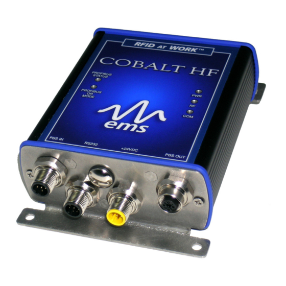
High Frequency Passive Radio Frequency Identification Controller
I
G
NSTALLATION
UIDE
How to Install and Setup
Cobalt HF-CNTL-PBS-02 RFID Controller
HF-CNTL-PBS-02 INSTALLATION GUIDE – REV. 03
Copyright © 2010 Datalogic Automation S.r.l., all rights reserved
HF-CNTL-PBS- 0 2 I N S T A L L A T I O N G U I D E – R E V . 0 3
P A G E 1 O F 2 3
Advertisement

Related Manuals for Datalogic Cobalt HF-CNTL-PBS-02

Summary of Contents for Datalogic Cobalt HF-CNTL-PBS-02
- Page 1 HF-CNTL-PBS-02 INSTALLATION GUIDE – REV. 03 Copyright © 2010 Datalogic Automation S.r.l., all rights reserved HF-CNTL-PBS- 0 2 I N S T A L L A T I O N G U I D E – R E V . 0 3...
- Page 2 FCC COMPLIANCE Modifications or changes to this equipment without the expressed written approval of Datalogic could void the autority to use the equipment. This device complies with PART 15 of the FCC Rules. Operation is subject to the following two conditions: (1) This device may not cause harmful interference, and (2) this device must accept any interference that may cause undesired operation.
- Page 3 RADIO COMPLIANCE ENGLISH Contact the competent authority responsible for the management of radio frequency devices of your country to verify any possible restrictions or licenses required. Refer to the web site: http://ec.europa.eu/enterprise/sectors/rtte/ for further information. ITALIANO Prendi contatto con l'autorità competente per la gestione degli apparati a radio frequenza del tuo paese, per verificare eventuali restrizioni o licenze.
-
Page 4: Chapter 1: Controller Information
V E R V I E W Welcome to the Cobalt HF-CNTL-PBS-02 RFID Controller – Installation Guide, this document will assist you in the installation and setup of the Cobalt HF-CNTL-PBS-02 RFID Controller. The Cobalt HF-CNTL-PBS-02 is a feature-rich, high frequency, Radio-Frequency Identification device that provides read/write RFID data transmission and control solutions to shop floor, item-level tracking and material handling applications. - Page 5 1.1.2 Power & Communications Interface Connection Type: Profibus Communication Interface: Profibus - DP Data Interface Connector: 5-pin, male M12 5-pin, female M12 Connector (for Connector (for Profibus data) Profibus data) Power Interface Connector: 5-pin, Male, M12 (for power) Additional Connector: 8-pin, Male M12 Connector for RS232 configuration support Maximum Cable Length:...
- Page 6 1 . 2 H F- S R FI D A O B A L T E R I E S N T E N N A S The Cobalt HF product family currently includes four different RFID antenna models. Because Cobalt HF Antennas are designed with different dimensions, they each generate unique RF field pattern and read/write range.
- Page 7 1.2.1 HF-ANT-1010-01 Antenna Dimensions Figure 1-3: HF-ANT-1010-01 Antenna Dimensions HF-CNTL-PBS- 0 2 I N S T A L L A T I O N G U I D E – R E V . 0 3 P A G E 7 O F 2 3...
- Page 8 1.2.2 HF-ANT-2020-01 Antenna Dimensions Figure 1-4: HF-ANT-2020-01 Antenna Dimensions HF-CNTL-PBS- 0 2 I N S T A L L A T I O N G U I D E – R E V . 0 3 P A G E 8 O F 2 3...
- Page 9 1.2.3 HF-ANT-3030-01 Antenna Dimensions Figure 1-5: HF-ANT-3030-01 Antenna Dimensions HF-CNTL-PBS- 0 2 I N S T A L L A T I O N G U I D E – R E V . 0 3 P A G E 9 O F 2 3...
- Page 10 1.2.4 HF-ANT-0750-01 Antenna Dimensions Figure 1-6: HF-ANT-0750-01 Antenna Dimensions HF-CNTL-PBS- 0 2 I N S T A L L A T I O N G U I D E – R E V . 0 3 P A G E 1 0 O F 2 3...
-
Page 11: Chapter 2: Controller Installation
CHAPTER 2: CONTROLLER INSTALLATION 2 . 1 R E P A R I N G F O R N S T A L L A T I O N 2.1.1 Power Requirements The Cobalt Controller requires an electrical DC supply voltage. See Technical Specifications for details. - Page 12 1.7 Nm or 15 lbs / inch ITEM DESCRIPTION Cobalt Controller (HF-CNTL-PBS-02) Cobalt Antenna (HF-ANT-1010-01) Washer (Spring Lock, M5, 18-8 SS) Screw (Socket Head Cap, M5 X 20mm, 18-8 SS) HF-CNTL-PBS- 0 2 I N S T A L L A T I O N G U I D E – R E V . 0 3 P A G E 1 2 O F 2 3...
- Page 13 2.2.1 Minimum Distance between Antennas When installing multiple Cobalt HF-Series Controllers/Antennas, refer to the table below to determine the recommended minimum distance to maintain between adjacent Cobalt Antennas. C O B AL T - 1 0 1 0 - 2 0 2 0 - 3 0 3 0 - 0 7 5 0 AN T E N N A...
- Page 14 2 . 3 H F- C NT L - PB S - 0 2 N S T A L L I N G T H E Note: review Section 2.1.2: “Installation Guidelines” prior to installing the controller. Attach the Cobalt HF Antenna to the Cobalt HF Controller as per the instructions in Section 2.2: “Connecting the Antenna.”...
- Page 15 C O M P O R T P AR AM E T E R D E F AU L T V AL U E Baud 9600 Data Bits Stop Bits Parity None Handshaking None Table 2-2: HF-CNTL-PBS-02 COM Port Default Settings 10.
- Page 16 2 . 4 A B L I N G N F O R M A T I O N Figure 2-1: 5-Pin, Male, M12 Connector (Profibus); 8-Pin, Male M12 Connector (for RS232 configuration); 5-Pin, Male, M12 Connector (Power) & 5-Pin, Female, M12 Connector (Profibus) 5- P M1 2 C...
- Page 17 8- P M1 2 C – R S 23 2 C A L E O N N E C T O R O N F I G U R A T I O N P I N # D E S C R I P T I O N NOT CONNECTED NOT CONNECTED NOT CONNECTED...
- Page 18 2.4.1 Profibus Interface Cable Schematic Figure 2-2: CBL-1438-XX (Cable Profibus 12MM, 5-Pin, M/F) Figure 2-3: CBL-1487 (5-Pin, Female, M12, Straight Field Mountable Connector) HF-CNTL-PBS- 0 2 I N S T A L L A T I O N G U I D E – R E V . 0 3 P A G E 1 8 O F 2 3...
- Page 19 ATTENTION: For operating instructions for the HF-CNTL-PBS-02 RFID Controller, refer to the: Cobalt HF-Series RFID Controllers – Operator’s Manual available online at: www.ems-rfid.com. Also available online at www.ems-rfid.com is Escort Memory Systems’ Cobalt Dashboard™ software utility. The RFID Dashboard is a Windows-based application that provides users with complete control over their EMS RFID hardware.
-
Page 20: Chapter 3: Technical Specifications
CHAPTER 3: TECHNICAL SPECIFICATIONS 3 . 1 C O B AL T H F CO NT RO L L E RS EL EC TR IC AL DC input Voltage Range 12-30VDC DC Input Current 500-300mA RA DIO Frequency 13,56MHz Air Interface ISO15693, ISO14443 Conducted Output Power CO MMU N IC ATI O N... - Page 21 EN V IR O N ME NT AL Operating Temperature -20° to 50° C ( -4° to 122° F ) Storage Temperature -20° to +70° C ( -4° to 158° F ) Humidity 90% non-condensing Protection Class IP65 3 . 2 H F A NT E N N AS EL E CTR IC AL All models...
- Page 22 E C H A N I C A L HF-ANT-1010-1 Dimensions 100x100x42mm ( 3.95x3.95x1.67in) Weight 280g ( 9.88oz ) HF-ANT-2020-1 Dimensions 200x200x42mm ( 7.87x7.87x1.67in) Weight 500g ( 17.64 oz ) HF-ANT-3030-1 Dimensions 300x300x42mm ( 11.81x11.81x1.67 oz ) Weight 740g ( 26.10 oz ) HF-ANT-0750-1 Dimensions 70x500x42mm ( 2.76x19.69x1.59in )
- Page 23 Datalogic Automation and excluded from this agreement. Under no circumstances shall Datalogic Automation be liable to Buyer, in contract or in tort, for any special, indirect, incidental, or consequential damages, expenses, losses or delay however caused.