Advertisement
Quick Links
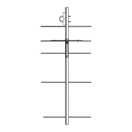
5 Element 144-148 MHz (Rear/Center Mount) Yagi,
Anti-Seize Compound – Apply a small amount of the supplied Anti-Seize Compound to the aluminum joints and
to the threads of the U-Bolts to prevent galling.
DSEDPM144-5LVA Rev 10/20
Directive Systems & Engineering
2702 Rodgers Terrace
Haymarket, VA 20169-1628
www.directivesystems.com
Model DSEDPM144-5LVA
ELECTRICAL SPECIFICATIONS
Frequency range: MHz ..................... 144-148
Gain: dBd........................................... 9.0
Impedance: Ohms.............................. 50
Connector type................................... Type N(F) UG-58/U
Front -to- back ratio: dB...................... 20
SWR: Typical at resonance................ ≅1.2:1
Beamwidth: -3 degrees
E- Plane ................................. 52°
-10 dB ................................. 89.6°
H- Plane ................................. 65°
Sidelobe level: decibels
E- Plane ................................. -17
H- Plane ................................. -16
Power rating, Continuous: Watts ...... 1500
Stacking Distance: in.(m)
E- Plane.................................. 72" (1.829)
H- Plane................................. 66" (1.676)
Boom length: in. (m.)........................... 67" (1.7)
Turning radius: in. (m.)........................ 34" (.863)
Weight Assembled: Lbs (kg.).............. 2.8 (1.27)
Max mast size: in. (cm.).......................2" (5.08)
Wind surface area: Ft
Wind Survival: Mph (km/hr)................. 100 (160)
PARTS LIST
Note: All hardware is Stainless Steel unless otherwise noted.
703-754-3876
MECHANICAL SPECIFICATIONS
2
2
(m.
) ............... 0.5 (.046)
Advertisement

Subscribe to Our Youtube Channel
Related Manuals for Directive Systems & Engineering DSEDPM144-5LVA


Summary of Contents for Directive Systems & Engineering DSEDPM144-5LVA
- Page 1 PARTS LIST Note: All hardware is Stainless Steel unless otherwise noted. Anti-Seize Compound – Apply a small amount of the supplied Anti-Seize Compound to the aluminum joints and to the threads of the U-Bolts to prevent galling. DSEDPM144-5LVA Rev 10/20...
- Page 2 The element bundle contains all of the elements needed for assembly. Take time to inventory each one and check off each dimension with Table 1. Some elements vary by a few millimeters, so extreme care in measuring is required here. Arrange elements in order of DSEDPM144-5LVA Rev 10/20...
- Page 3 The rear side, with the tabs going outward, is the side that faces you. It is the side that goes face down into the element tool. Keeper Front side Keeper Rear side DSEDPM144-5LVA Rev 10/20...
- Page 4 Place the T-arm support bracket on next, then the connector L bracket (connector facing forward!). Next place a #8 split lock washer and a nut and tighten. Install supplied 3/8” plastic plug in the driven element access hole and the 1/2” ends caps. DSEDPM144-5LVA Rev 10/20...
- Page 5 P a g e FIGURE 4. DSEDPM144-5LVA Rev 10/20...
- Page 6 P a g e DSEDPM144-5LVA Rev 10/20...
- Page 7 T-match wire orientation. In the above drawing, the center pin goes to the right hand side of the antenna as viewed from the back of the connector. Make sure both antennas do the same! Proper phase relationship is very important here! DSEDPM144-5LVA Rev 10/20...
- Page 8 SWR. caps on ends of boom. FIGURE 6. FIGURE 7. Before moving on to the following step, apply a small amount of the supplied Anti-Seize Compound to the threads of the U-Bolts to prevent galling. DSEDPM144-5LVA Rev 10/20...
- Page 9 DO NOT, UNDER ANY CIRCUMSTANCES, APPLY ANY TYPE OF SEALANT OR COATING TO THE DRIVEN ® ELEMENT, T-ARMS OR CONNECTOR ASSEMBLY, OTHER THAN KRYLON CLEAR COAT. ANY OTHER COATING WILL ADVERSELY AFFECT THE SWR AND VOID YOUR WARRANTY. DSEDPM144-5LVA Rev 10/20...
- Page 10 | 10 Using the dimensions supplied, your SWR should match our plot. This will complete the assembly of your DSEDPM144-5LVA. The construction of this antenna will provide many years of consistent performance with no degradation of performance due to corrosion and weathering.
- Page 11 ANY ANTENNA THAT HAS BEEN MODIFIED WILL BE SUBJECT TO A RESTOCKING CHARGE. IF AN ANTENNA IS SO MODIFIED AS TO MAKE IT UNUSABLE, DIRECTIVE SYSTEMS RESERVES THE RIGHT TO REFUSE TO ACCEPT THE ANTENNA FOR RETURN. DSEDPM144-5LVA Rev 10/20...
Need help?
Do you have a question about the DSEDPM144-5LVA and is the answer not in the manual?
Questions and answers