Advertisement
Quick Links
DSEFO144-12 Rev 8/19
Directive Systems & Engineering
Haymarket, VA 20169-1628
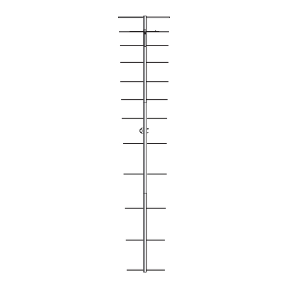
12 Element 2.5 wl. K1FO Designed Yagi, Model DSEFO144-12
Frequency range: MHz ...................... 144-146
Gain: dBd........................................... 12.6
Impedance: Ohms.............................. 50
Connector type................................... Type N(F) UG-58/U
Front -to- back ratio: dB...................... 23
SWR: Typical at resonance................ ≅1.2:1
Beamwidth: degrees
Sidelobe level: decibels
Power rating, Continuous: Watts ...... 1000
Stacking Distance: ft.(m)
Boom length: ft. (m.)........................... 17'4" (5.28)
Turning radius: in. (m.)........................ 10'4" (3.15)
Weight Assembled: Lbs (kg.).............. 9.5 (4.32)
Max mast size: in. (cm.)....................... 2" (5.08)
Wind surface area: Ft (m. ) ................. 1.5 (.14)
Wind Survival: Mph (km/hr)................. 100 (160)
Note: All hardware is Stainless Steel, unless otherwise noted.
2702 Rodgers Terrace
www.directivesystems.com
703-754-3876
ELECTRICAL SPECIFICATIONS
E- Plane ................................. 34°
H- Plane ................................. 37°
E- Plane ................................. -19
H- Plane ................................. -16
E- Plane.................................. 11'7" (3.53)
H- Plane................................. 10'8" (3.25)
MECHANICAL SPECIFICATIONS
PARTS LIST
Advertisement

Subscribe to Our Youtube Channel
Related Manuals for Directive Systems & Engineering DSEFO144-12


Summary of Contents for Directive Systems & Engineering DSEFO144-12
- Page 1 Directive Systems & Engineering 2702 Rodgers Terrace Haymarket, VA 20169-1628 www.directivesystems.com 703-754-3876 12 Element 2.5 wl. K1FO Designed Yagi, Model DSEFO144-12 ELECTRICAL SPECIFICATIONS Frequency range: MHz ...... 144-146 Gain: dBd........... 12.6 Impedance: Ohms......50 Connector type........Type N(F) UG-58/U Front -to- back ratio: dB...... 23 SWR: Typical at resonance....
- Page 2 Tools needed: #2 Phillips screwdriver ¼” flat blade screwdriver large needle nosed pliers keeper installation tool (supplied with kit) ruler with metric millimeter markings marking pencil BEFORE INSTALLING YOUR NEW ANTENNA, PLEASE BE SURE TO READ THE ENCLOSED WARNING PAMPHLET. DSEFO144-12 Rev 8/19...
- Page 3 Install a black insulator in each side of the boom piece at the starting end, and slide the correct element through the two insulators. Obtain a second keeper and install that keeper on the opposite end of element #1 from the pre-installed keeper. DSEFO144-12 Rev 8/19...
- Page 4 Place the T-arm support bracket on next, then the connector L bracket (connector facing forward!). Next place a #8 internal tooth lock washer and a nut and tighten. Install 3/8” plastic plug in the driven element access hole. DSEFO144-12 Rev 8/19...
- Page 5 P a g e FIGURE 4. DSEFO144-12 Rev 8/19...
- Page 6 P a g e DSEFO144-12 Rev 8/19...
- Page 7 T-match wire orientation. In the above drawing, the center pin goes to the right hand side of the antenna as viewed from the back of the connector. Make sure both antennas do the same! Proper phase relationship is very important here! DSEFO144-12 Rev 8/19...
- Page 8 Slide the shorting bars over the ends of the driven elements and over the T arms and measure from the T arm mounting screws to the inside edge of the shorting bars and set it at 160 mm. FIGURE 6. DSEFO144-12 Rev 8/19...
- Page 9 As a general rule, the slower drying sprays tend to be more enduring. Rustoleum "Clear Seal" or Krylon clear spray are recommended. A few light coats work better than one big one. DSEFO144-12 Rev 8/19...
- Page 10 CLEAR COAT. ANY OTHER COATING WILL ADVERSELY AFFECT THE SWR AND VOID YOUR WARRANTY. This will complete the assembly of your DSEFO144-12. The construction of this antenna will provide many years of consistent performance with no degradation of performance due to corrosion and weathering.
Need help?
Do you have a question about the DSEFO144-12 and is the answer not in the manual?
Questions and answers