Table of Contents
Advertisement
Quick Links
Operation, Parts
FinishPro II 395 PC
Airless/Air-Assisted Sprayer
For professional use only.
Not approved for use in explosive atmospheres or hazardous locations.
For portable application of architectural paints and coatings.
Models: 17C417, 17C418, 17C421, 17C320, 17C321
3300 psi (228 bar, 22.8 MPa) Maximum Working Pressure
See page 3 for additional model information.
Important Safety Instructions
Read all warnings and instructions in this manual and related manuals.
Be familiar with the controls and the proper usage of the equipment.
Save these instructions.
Related Manuals
Gun - 333182
Use only genuine Graco replacement parts.
The use of non-Graco replacement parts may void warranty.
Pump - 334599
334730F
ti25382a
EN
Advertisement
Table of Contents

Related Manuals for Graco FinishPro II 395 PC


Summary of Contents for Graco FinishPro II 395 PC
-
Page 1: Important Safety Instructions
Read all warnings and instructions in this manual and related manuals. Be familiar with the controls and the proper usage of the equipment. Save these instructions. Related Manuals Gun - 333182 Pump - 334599 ti25382a Use only genuine Graco replacement parts. The use of non-Graco replacement parts may void warranty. -
Page 2: Table Of Contents
Graco Standard Warranty ........ -
Page 3: Models
Models Models Model 110474 17C417 FinishPro II 395 PC Certified to CAN/CSA C22.2 No. 68 Conforms to UL 1450 17C418 FinishPro II 395 PC CEE 7/7 230 Europe FinishPro II 395 PC 17C421 Multicord 17C320 FinishPro II 395 PC Asia/ANZ... -
Page 4: Warnings
Warnings Warnings The following warnings are for the setup, use, grounding, maintenance, and repair of this equipment. The exclamation point symbol alerts you to a general warning and the hazard symbols refer to procedure-specific risks. When these symbols appear in the body of this manual or on warning labels, refer back to these Warnings. - Page 5 All parts of the spray system, including the pump, hose assembly, spray gun, and objects in and around the spray area shall be properly grounded to protect against static discharge and sparks. Use Graco conductive or grounded high-pressure airless paint sprayer hoses.
- Page 6 Check hoses and parts for signs of damage. Replace any damaged hoses or parts. • This system is capable of producing 3300 psi. Use Graco replacement parts or accessories that are rated a minimum of 3300 psi. • Always engage the trigger lock when not spraying. Verify the trigger lock is functioning properly.
- Page 7 Warnings ELECTRIC SHOCK HAZARD This equipment must be grounded. Improper grounding, setup, or usage of the system can cause electric shock. • Turn off and disconnect power cord before servicing equipment. • Connect only to grounded electrical outlets. • Use only 3-wire extension cords. •...
-
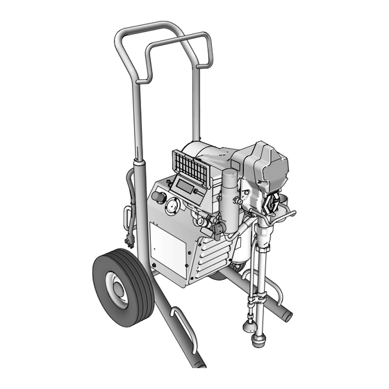
Page 8: Component Identification
Component Identification Component Identification ti25536a Fluid Intake Power/Function Selector Pump Pressure Control Fluid Outlet Air Hose Connection Hanger Prime Valve Filter Gun Filter Finger Guard / TSL Fill Point Tip Guard Pail Hook Spray Tip Display Gun Air Regulator Airless Hose Sprayer Air Pressure Regulator Power Cord Air Pressure Gauge... -
Page 9: Grounding
Grounding Grounding Do not place pail on a non-conductive surface such as paper or cardboard which interrupts grounding continuity. The equipment must be grounded to reduce the risk of static sparking and electric shock. An electric or static spark can cause fumes to ignite or explode. An improper ground can cause electric shock. -
Page 10: Pressure Relief Procedure
Pressure Relief Procedure Pressure Relief Procedure Engage trigger lock. Follow the Pressure Relief Procedure whenever you see this symbol. ti25450a Turn pressure control to lowest setting. Disengage trigger lock. This equipment stays pressurized until pressure is manually relieved. To help prevent serious injury from pressurized fluid, such as skin injection, splashed fluid and moving parts, follow the Pressure... -
Page 11: Trigger Lock
Pressure Relief Procedure Put drain tube in pail. Turn prime valve VERY SLOWLY loosen tip guard retaining nut or hose end coupling to down. Leave prime valve in down (drain) relieve pressure gradually. position until you are ready to spray again. -
Page 12: Setup
When unpacking sprayer for the first time or after long term storage perform setup procedure. When first setup is performed remove shipping plug from fluid outlet. Connect Graco airless hose to fluid ti25412a outlet. Use wrenches to tighten Use wrenches to tighten securely. - Page 13 Setup Make certain SELECTOR switch is OFF. ti25541a Plug power supply cord into a properly grounded electrical outlet. ti24638a Fill throat packing nut with TSL to prevent premature packing wear. Do this ti24651a daily or each time you spray. 10. Turn prime valve down. Place the TSL bottle nozzle into the top center opening in the grill at the front of the sprayer.
- Page 14 Setup 11. Place fluid intake with drain tube in 20. Set SELECTOR switch to AIRLESS grounded metal pail partially filled with position. flushing fluid. See Grounding, page 9. 21. Turn prime valve horizontal. Disengage trigger lock. NOTE: New sprayers are shipped with 22.
-
Page 15: Startup
Startup Startup Perform Pressure Relief Procedure, page 10. Turn pressure control to lowest pressure. 15 s ti24645a Turn prime valve horizontal. Disengage trigger lock. ti25345a Set SELECTOR switch to AIRLESS position. ti25455a Hold gun against grounded metal waste pail. Trigger gun until paint appears. ti25537a Place fluid intake in paint pail. - Page 16 Startup Inspect for leaks. If leaks occur, perform Move gun to paint pail and trigger for 20 Pressure Relief Procedure, page 10, seconds. Release trigger and allow then tighten all fittings and repeat Startup sprayer to build pressure. Engage procedure. If there are no leaks continue trigger lock.
-
Page 17: Operation
Operation Operation Spray Tip Installation NOTICE If air cap is not fully installed on gun, fluid pressure can force paint into air line and dam- age sprayer. Perform Pressure Relief Procedure, page 10. Engage trigger lock. ti25475a Install air cap over end of gun. Hand tighten. -
Page 18: Spray
Operation Spray Open gun air regulator all the way. When a RAC X™ FF LP Fine Finish Low Pressure reversible spray tip is used, spraying pressure can be lowered. Spraying at a lower pressure results in less overspray and reduces spray tip wear. Adjust the sprayer pressure to minimize overspray. -
Page 19: Airless Spraying
Operation Trigger gun. While spraying, turn air Airless Spraying regulator knob to increase pressure until tails disappear. Set SELECTOR switch to AIRLESS position. ti25547a Use gun air regulator to fine tune spray ti25482a pattern. Prime pump, see Startup, page 15. Start with pressure turned to the lowest setting. -
Page 20: Clear Tip Clog
Operation Clear Tip Clog Perform Pressure Relief Procedure, page 10. Engage trigger lock. ti25450a Engage trigger lock. Return spray tip to original position. Disengage trigger lock and continue spraying. Flat tip: Remove and clean guard and tip RAC Tip: Proceed to next step. Rotate tip 180°. -
Page 21: Digital Display
Operation Digital Display Press and hold display button to change pressure units (psi, bar, or MPa). Most models are equipped with a digital display. This section explains how to use this feature. Pressure Display Perform Pressure Relief Procedure, page 10. Plug sprayer into grounded outlet. - Page 22 Operation To enter Stored Data Mode, press and Press display button again to display hold display button and set SELECTOR Data Point 3. This will be the last error switch to AIRLESS position. code. ti2824a To erase last error code, press and hold display button.
-
Page 23: Cleanup
Operation Cleanup Place fluid intake in flushing fluid. Use water for water base paint and mineral spirits for oil-based paint. Place drain tube in waste pail. Perform Pressure Relief Procedure, page 10. Remove tip guard and spray tip. For additional information, see separate gun manual. - Page 24 Operation While continuing to trigger gun, turn 10. With prime valve horizontal. Trigger gun prime valve down. Then, release gun into flushing pail to purge fluid from hose. trigger. Allow flushing fluid to circulate 11. Set SELECTOR switch to AA until fluid comes out of drain tube clear.
- Page 25 Operation 14. Turn pressure control knob to OFF and 16. If flushing with water, flush again with set SELECTOR switch to OFF position. mineral spirits or Pump Armor to leave a Disconnect power to sprayer. protective coating to prevent freezing or corrosion.
-
Page 26: Maintenance
Maintenance Maintenance Routine maintenance is important to ensure proper operation of your sprayer. Maintenance includes performing routine actions which keep your sprayer in operation and prevents trouble in the future. Activity Interval Inspect/clean sprayer filter, fluid inlet strainer, and gun filter. Daily or each time you spray Inspect motor shield vents for blockage. -
Page 27: Troubleshooting
Troubleshooting Troubleshooting Mechanical/Fluid Flow Follow Pressure Relief Procedure, Check all possible problems and causes page 10, before checking or repairing. before disassembling the unit. What to Check What to Do If check is OK, go to next When check is not OK, Problem check refer to this column... - Page 28 Troubleshooting What to Check What to Do If check is OK, go to next When check is not OK, Problem check refer to this column Pump output is low Pump rod damage. Repair pump. See pump manual. Low stall pressure. Turn pressure knob fully clockwise.
- Page 29 Troubleshooting What to Check What to Do If check is OK, go to next When check is not OK, Problem check refer to this column Fluid is spitting from gun Air in pump or hose. Check and tighten all fluid connections.
-
Page 30: Electrical
Troubleshooting Electrical View digital display or remove control box cover to view control board status light. To determine which code (or any Symptom: Sprayer does not run, stops other code besides voltage supply) refer running, or will not shut off. to the control board status light. - Page 31 Troubleshooting Problem What to Check How to check Check transducer or transducer Sprayer does not run at all Make sure there is no pressure in the system (see Pressure connections Relief Procedure, page 10). Display shows E=02 Check fluid path for clogs, such as clogged filter.
- Page 32 Troubleshooting Problem What to Check How to check Sprayer does not run at all Check voltage supply to the Set SELECTOR switch to OFF sprayer (control board is and disconnect power to sprayer. detecting a multiple voltage Locate a good voltage supply to Display shows E=04 surges).
- Page 33 Troubleshooting Problem What to Check How to check 6.Connect the Red and Black leads from the motor to an Ohm meter. Rotate the motor while checking for opens. If an open is found replace the motor. BLACK (-) RED (+) YELLOW 1-3 ohms ti24723a...
- Page 34 Troubleshooting Problem What to Check How to check 8.Use an Ohm meter to check motor for shorts. Connect (–) meter lead to motor case. Move the (+) meter lead to each motor wire. Meter should read open on all wires. GROUND BLACK YELLOW...
- Page 35 Troubleshooting Problem What to Check How to check Basic electrical problems Motor leads are securely Replace loose terminals; crimp fastened and properly mated to leads. Be sure terminal are firmly connected. Clean circuit board terminals. Securely reconnect leads. For loose motor brush lead Tighten terminal screws.
- Page 36 Troubleshooting Sprayer Will Not Run (See following page for steps) Sprayer Will Not Run (see following pages for steps) Remove Control box cover. Turn sprayer ON. Observe control board status light on See Step 1. Do you control board (see page 27). have over 100 VAC (220 VAC for 230v units)? No Light...
- Page 37 Troubleshooting Step 1: Step 3: Plug Power cord in and turn Check motor thermal switch. switch ON. Connect probes Unplug yellow wires. Meter to L and N on control board. should read continuity. Turn meter to AC Volts. NOTE: Motor should be cool during reading.
- Page 38 Troubleshooting Sprayer Will Not Shut Off (down) and set SELECTOR switch OFF. Perform Pressure Relief Procedure, Remove control box cover so the page 10. Leave prime valve open control board status light can be viewed if available. Troubleshooting Procedure Troubleshooting Procedure Plumb pressure gauge into paint hose, Mechanical problem: plug sprayer in, and turn power switch ON.
-
Page 39: Sprayer
Sprayer Sprayer Ref. Torque See page 44 for Compressor parts. 140-160 in-lb (15.8 - 18.1 N•m) 30-35 in-lb (3.4 - 4.0 N•m) See page 42. ti25385a 334730F... - Page 40 Sprayer Ref. Torque 140-160 in-lb (15.8 - 18.1 N•m) 30-35 in-lb (3.4 - 4.0 N•m) Hammer tight 25-30 ft-lb (33.9 - 40.7 N•m) 22 110 ti25384a 334730F...
-
Page 41: Sprayers Parts List
Sprayer Sprayers Parts List Ref. Part Description Qty. Ref. Part Description Qty. 24U249 FRAME, cart, hi, AA 117501 SCREW, mach, slot hex wash 17C992 TUBE, suction includes 14, 57, 84, 102, 120 103413 PACKING, o-ring GUN, assy, AA G40 17C539 COVER, front, painted 262929 Models 17C417, 17C321... -
Page 42: Control And Filter
Control and Filter Control and Filter Ref. Torque 140-160 in-lb (15.8 - 18.1 N•m) 30-35 in-lb (3.4 - 4.0 N•m) 20-25 in-lb (2.3 - 2.8 N•m) 37-43 ft-lb (50.2 - 58.3 N•m) 130-150 in-lb (14.7 - 16.9 N•m) ti25528a 334730F... -
Page 43: Control And Filter Parts List
Control and Filter Control and Filter Parts List Ref. Part Description Qty. Ref. Part Description Qty. 15M176 Model 17C418, 117828 PACKING, o-ring 17C421, 17C320, 111457 PACKING, o-ring 17C321 111600 PIN, grooved CONTROL BOARD 277364 GASKET, seat, valve 288840 Model 17C417 115494 SCREW, mach, phillips 288842... -
Page 44: Compressor
Compressor Compressor Ref. Torque 60-85 in-lb (6.8 - 9.6 N•m) 95-100 in-lb (10.7 - 11.3N•m) 94 21 ti25529a 334730F... -
Page 45: Compressor Parts List
Compressor Compressor Parts List Ref. Part Description Qty. Ref. Part Description Qty. 108 15B822 TUBE, air 115494 SCREW, mach, Phillips 195551 RETAINER, plug, 120643 GAUGE, pressure, adapter panel mount, 1.5 16X530 CORD, pwr, comp. 127330 REGULATOR, air, 1/4 female end in. -
Page 46: Wiring Diagrams
Wiring Diagrams Wiring Diagrams 120V, US/110V, UK BLACK SOLENOID BLACK TIMER WHITE WHITE COMPRESSOR ON/OFF SWITCH YELLOW BLACK TO COMPRESSOR POTENTIOMETER BLUE BLACK GREEN TRANSDUCER POWER PLUG WHITE RED (+) BLACK/ WHITE (-) 2X WHITE PRESSURE FROM MOTOR SWITCH ti22659b DIGITAL DISPLAY 334730F... -
Page 47: 230V
Wiring Diagrams 230V BLACK SOLENOID BLACK TIMER WHITE WHITE COMPRESSOR ON/OFF SWITCH BLACK TO COMPRESSOR POTENTIOMETER BLUE BLUE BLACK GREEN TRANSDUCER POWER PLUG WHITE RED (+) BLACK/ WHITE (-) FERRITE BEAD 2X WHITE PRESSURE FROM SWITCH MOTOR ti22660b DIGITAL DISPLAY 334730F... -
Page 48: Technical Specifications
Technical Specifications Technical Specifications FinishPro II 395 PC Metric Sprayer Power requirements 100/120V AC, 50/60 Hz, 230V AC, 50/60 Hz, 10A, 15A, 1Ø 1Ø Generator Minimum 4000 W Max tip size US / UK 0.021 0.021 Europe / Asia/Australia... - Page 49 Technical Specifications FinishPro II 395 PC Metric Wetted materials on all models zinc- and nickel-plated carbon steel, nylon, stainless steel, PTFE, Acetal, leather, UHMWPE, aluminum, tungsten carbide, polyethylene, fluoroelastomer, urethane Notes * Startup pressures and displacement per cycle may vary based on suction condition, discharge head, air pressure, and fluid type.
-
Page 50: Graco Standard Warranty
Graco’s written recommendations. This warranty does not cover, and Graco shall not be liable for general wear and tear, or any malfunction, damage or wear caused by faulty installation, misapplication, abrasion, corrosion, inadequate or improper maintenance, negligence, accident, tampering, or substitution of non-Graco component parts. -
Page 51: Graco Information
Graco Information Graco Information For the latest information about Graco products, visit www.graco.com. For patent information, see www.graco.com/patents. TO PLACE AN ORDER, contact your Graco distributor or call 1-800-690-2894 to identify the nearest distributor. 334730F... - Page 52 Original instructions. This manual contains English. MM 334730 Graco Headquarters: Minneapolis International Offices: Belgium, China, Japan, Korea GRACO INC. AND SUBSIDIARIES • P.O. BOX 1441 • MINNEAPOLIS MN 55440-1441 • USA Copyright 2015, Graco Inc. All Graco manufacturing locations are registered to ISO 9001. www.graco.com...
Need help?
Do you have a question about the FinishPro II 395 PC and is the answer not in the manual?
Questions and answers