
Related Manuals for QCT QuantaMesh T1048-LB9

Summary of Contents for QCT QuantaMesh T1048-LB9
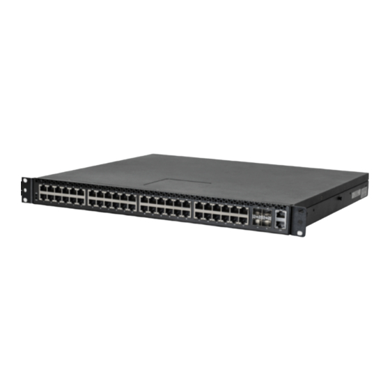
- Page 1 QuantaMesh T1048-LB9 Network Switch (Layer 2/3 Managed 1/10G Switch) Installation Guide...
-
Page 2: Table Of Contents
Contents Chapter 1: Safety and Regulatory Information ......1 1.1 Copyright ...................2 1.2 About the Manual ..............2 1.3 Intended Application Uses ............2 1.4 Safety Information ..............2 1.4.1 Switch Safety Information ..........2 1.4.2 Installation Assembly Safety Instructions .......4 1.4.3 Site Selection ..............4 1.4.4 Equipment Handling Practices ........5 1.4.5 Power and Electrical Warnings ........5 1.4.6 Power Cord Warnings .............6... - Page 3 Contents 4.4 Upgrade the Firmware .............30 4.4.1 Initialization Stage ............30 4.4.2 Upgrade the Firmware Image File ........31 4.5 Manually Install Vendor OS .............32 Chapter 5: Troubleshooting ............34 5.1 Troubleshooting ...............35 5.1.1 Diagnostic Switch Indicator ...........35 5.1.2 Power and Cooling Problems ........35 5.1.3 Installation ..............35 5.1.4 In-Band Access ............36 5.2 Replace the Power Supply Unit ..........36...
- Page 4 List of Figures Figure 2-1: Front Panel View ............13 Figure 2-2: Base-T Port LEDs ............13 Figure 2-3: SFP+ Port LEDs ............14 Figure 2-4: Function Port LEDs ............15 Figure 2-5: Management Port LEDs ..........15 Figure 2-6: Rear Panel View ............16 Figure 3-1: Install Switch on Rack (Without Rail) ......19 Figure 3-2: Holes Alignment ............19 Figure 3-3: Secure Position .............19 Figure 3-4: Pull Out Rack Rail ............20...
- Page 5 List of Tables Table 1-1: Manual Conventions Icon ..........2 Table 1-2: Product Regulatory Compliance Markings .....11 Table 2-1: Base-T Port LEDs ............13 Table 2-2: SFP+ Port LEDs .............14 Table 2-3: Function and Management Port LEDs ......15 Table 2-4: Power Supply LEDs ............16 Table 5-1: Troubleshooting Tips ............35...
-
Page 6: Chapter 1: Safety And Regulatory Information
Chapter 1: Safety and Regulatory Information This chapter contains important information on safety and regulatory, as well as conventions used in this installation guide. Read this guide before installing and operating the system. -
Page 7: Copyright
Safety and Regulatory Information Copyright All specifications and figures are subject to change without prior notice. Actual products may look different from the photos. All trademarks and logos mentioned in this guide are the properties of their respective holders. Copyright © 2017 Quanta Computer Inc. All rights reserved. About the Manual This installation guide is meant for network administrators with inept knowledge in network management. - Page 8 Safety and Regulatory Information Follow the safety guidelines below to ensure personal safety and protect the system and the working environment from potential damage. CAUTION: The power supplies in the system may produce high voltages and energy hazards which can cause bodily harm. Do not remove the covers and access any of the components inside the system.
-
Page 9: Installation Assembly Safety Instructions
Safety and Regulatory Information • Observe extension cable and power strip ratings. Ensure that the total ampere rating of all products plugged into the extension cable or power strip does not exceed 80% of the ampere ratings limit for the extension cable or power strip. •... -
Page 10: Equipment Handling Practices
Safety and Regulatory Information • Provided with a properly grounded wall outlet. • Provided with sufficient space to access the power supply cord(s), because they serve as the product’s main power disconnect. • Provided with either two independent AC power sources or two independent phases from a single source. 1.4.4 Equipment Handling Practices Reduce the risk of personal injury or equipment damage: •... -
Page 11: Power Cord Warnings
Safety and Regulatory Information 1.4.6 Power Cord Warnings If an AC power cord was not provided with your product, purchase one that is approved for use in your country. CAUTION: To avoid electrical shock or fire, check the power cord(s) that will be used with the product as follows: • Do not attempt to modify or use the AC power cord(s) if they are not the exact type required to fit into the grounded electrical outlets. -
Page 12: Rack Mount Warnings
Safety and Regulatory Information CAUTION: Unless you are adding or removing a hot-plug component, allow the system to cool before opening the covers. To avoid the possibility of coming into contact with hot component(s) during a hot-plug installation, be careful when removing or installing the hot-plug component(s). CAUTION: To avoid injury do not contact moving fan blades. If your system is supplied with a guard over the fan, do not operate the system without... -
Page 13: Other Hazards
Safety and Regulatory Information 1.4.9 Other Hazards 1.4.9.1 Battery Replacement CAUTION: There is the danger of explosion if the battery is incorrectly replaced. When replacing the battery, use only the battery recommended by the equipment manufacturer. CAUTION: Dispose of batteries according to local ordinances and regulations. CAUTION: Do not attempt to recharge a battery. -
Page 14: Regulatory And Compliance Information
Safety and Regulatory Information Regulatory and Compliance Information 1.5.1 Electromagnetic Compatibility Notices 1.5.1.1 FCC Verification Statement (USA) This device complies with Part 15 of the FCC Rules. Operation is subject to the following two conditions: (1) this device may not cause harmful interference, and (2) this device may accept any interference received, including interference that may cause undesired operation. This equipment has been tested and found to comply with the limits for a Class A digital device, pursuant to part 15 of the FCC Rules. - Page 15 Safety and Regulatory Information 1.5.1.4 CCC Statement 1.5.1.5 Regulated Specified Components To maintain the UL listing and compliance to other regulatory certifiications and/or declarations, the following regulated components must be used and conditions adhered to. Interchanging or use of other component will void the UL listing and other product certifications and approvals. Updated product information for configurations can be found on the site at the following URL: http://www.QuantaQCT.com If you do not have access to the Web address, please contact your local representative. •...
-
Page 16: Product Regulatory Compliance Markings
Safety and Regulatory Information 1.5.2 Product Regulatory Compliance Markings This product is marked with the following product certification markings: Table 1-2: Product Regulatory Compliance Markings Regulatory Region Marking Compliance cULus Listing USA / Canada Marks CE Mark Europe This device complies with Part 15 of the FCC Rules. FCC Marking Operation of this device is subject to the following two (Class A) conditions:... -
Page 17: Chapter 2: Introduction
Chapter 2: Introduction The QuantaMesh T1048-LB9 is a high performance layer 2/3/4 Ethernet switch with 48 10Base-T/100Base-TX/1000Base-T ports and 4 dual speed 1GbE/10GbE SFP+ ports in a compact rack unit size. The switch boasts of comprehensive network management and IP multicast functions. -
Page 18: Front Panel
Introduction Front Panel The following figures show the front panel of the switch. Figure 2-1: Front Panel View SFP+ Ports Base-T Ports Base-T Port LEDs SFP+ Port LEDs Console Port Power Status SFP+ Ports Base-T Ports Base-T Port LEDs Management Port 2.1.1 LED Description The following tables describe the LEDs on the front of the switch. 2.1.1.1 Base-T Port LEDs Figure 2-2:... -
Page 19: Figure 2-3: Sfp+ Port Leds
Introduction 2.1.1.2 SFP+ Port LEDs Figure 2-3: SFP+ Port LEDs Speed Link/Activity (LED# 50) (LED# 50) Speed Link/Activity (LED# 51) (LED# 51) NOTE: is the LED indicator for the upper row ports. is the LED indicator for the lower row ports. Table 2-2: SFP+ Port LEDs Description... -
Page 20: Figure 2-4: Function Port Leds
Introduction 2.1.1.3 Function and Management Port LEDs Figure 2-4: Function Port LEDs Power Status Power Status Figure 2-5: Management Port LEDs Speed Link/Activity Table 2-3: Function and Management Port LEDs Description Status • Yellow : System failure. Power • Green : All DC power good. -
Page 21: Rear Panel
Introduction Rear Panel The following figure shows the rear panel of the switch. Figure 2-6: Rear Panel View AC Power Connector AC Power Connector (with Plug Retainer) (with Plug Retainer) Handle Handle PSU2 PSU1 Fan Assembly PSU2 LED PSU1 LED The switch has two Power Supply Units (PSU) and four fan modules. The fan modules can be built in as back-to-front or front-to-back depending on customer requirements. -
Page 22: Chapter 3: Hardware Installation
Chapter 3: Hardware Installation This chapter describes the following topics: • Unpack the Hardware • Install the Switch • Connect to Power • Check the Installation • Connect Equipment • Connect to Console Port • Connect to Management Port... -
Page 23: Unpack The Hardware
Hardware Installation Unpack the Hardware Ensure all items are included in the package before starting the installation. NOTE: The packing box is heavy. It is recommended for two persons to carry the box and perform the installation. Place the box on a flat and stable surface and cut the straps securing the box. Remove the hardware and place it on a flat and clean surface. Remove all other items from the box. Inspect each item to make sure all items are included and free from damage (see “Select the Location”... -
Page 24: Install The Switch
Hardware Installation 3.2.1.2 Items Required for Installation The following items are required for installing, configuring, and connecting the switch: • A workstation • Ethernet cable • Console cable • SFP+ modules • Phillips screwdriver 3.2.2 Install the Switch 3.2.2.1 Install in a Rack You can install the switch in most standard 19-inch (48.3-cm) racks. Without Rail Installation Align the built-in mounting ear to the rack holes and secure them with screws. -
Page 25: Figure 3-4: Pull Out Rack Rail
Hardware Installation Pull out the internal rail. Figure 3-4: Pull Out Rack Rail Align the brackets to the rail holes and secure them with screws. Figure 3-5: Install Switch on Rail... -
Page 26: Connect To Power
Hardware Installation Connect to Power The switch has two Power Supply Units (PSU). Each PSU has an AC power connector. Depending on your needs, you may opt to use one or both PSUs at a time. To connect the switch to a power source, do the following: Connect one end of the AC power cord to an AC power connector. -
Page 27: Sfp+ Port
Hardware Installation To connect to the Base-T port, do the following: Connect one end of an Ethernet cable to the Base-T port. Figure 3-7: Connect to Base-T Port Connect the other end of the Ethernet cable to a network. The Base-T port LED (Link/Activity LED) lights green when the network link is established. NOTE: Ethernet cables are not included in the package. -
Page 28: Figure 3-9: Connect Sfp+ Module
Hardware Installation The 4 SFP+ ports support 10-gigabit IEEE 802.3ae Ethernet for fiber mediums. To install an SFP+ module, do the following: Slide the SFP+ module into an SFP+ port. Figure 3-9: Connect SFP+ Module Push completely until the module locks into place. Repeat the above procedures to install additional SFP+ modules. The SFP+ port LED lights green when the network link is established. -
Page 29: Connect To Console Port
Hardware Installation Connect to Console Port The console port is used for setting up and managing the switch via a connection to a console terminal or PC using a terminal emulation program. You can connect the switch to a terminal or PC using the supplied console cable (RJ-45 male to RS-232 female cable) for serial communication. -
Page 30: Connect To Management Port
Hardware Installation Connect to Management Port The switch has one management port. The management port is a dedicated port interface which is segregated from data traffic crossing other downlink or uplink ports. The port supports auto- negotiation. If the attached device also supports auto-negation, the transmission can operate in either half or full duplex, and data rate can be in 10Mbps, 100Mbps, or 1000Mbps. Telnet, SNMP, and Web browser utility can all go through this port for local or remote management after the IP address, subnet mask, and default gateway are properly configured. -
Page 31: Chapter 4: Initial Configuration
Chapter 4: Initial Configuration This chapter describes the following topics: • Initial Configuration Process • Configure the IP Address • Manage the Switch • Upgrade the Firmware • Manually Install Vendor OS... -
Page 32: Initial Configuration Process
Initial Configuration The following pages in this section are showing the IP address configuration and firmware upgrade SOP of Quanta runtime image. Initial Configuration Process When using the switch for the first time, configuration must be carried out through a console. Perform the following steps to configure the switch: Connect a terminal to the console port. Manually configure the IP Address by CLI. Manage the switch. Configure the IP Address You can configure the switch with a static IP address or use a Dynamic Host Configuration Protocol (DHCP) server to automatically obtain an IP address for the switch. For the first time configuration, it is recommended to set the IP address manually. 4.2.1 Set IP Address Manually To set the IP address of the switch manually, perform the following: Connect the switch to a computer with a terminal emulation program via the Console port. -
Page 33: Obtain Ip Address By Dhcp
Initial Configuration Set the service port IP address (in the example below, the service port IP address is set to 192.168.2.1). Configure Serviceport protocol none Serviceport ip 192.168.2.1 255.255.255.0 <gateway> exit Figure 4-2: Set Service Port IP Screen (Switch) (Switch) (Switch) (Switch) (Switch) -
Page 34: Manage The Switch
Initial Configuration Manage the Switch After the initial configuration, you may manage and monitor network activity by CLI or SNMP management, or by using the Web browser utility. 4.3.1 CLI Management The Command Line Interface (CLI) is administered when the terminal is directly connected to the Console port of the switch. This is an out-of-band connection, which means that it is on a different circuit than normal network communications, and thus works even when the network is down. -
Page 35: Upgrade The Firmware
Initial Configuration Upgrade the Firmware The switch firmware is continuously being upgraded to meet more networking demands. It is recommended to upgrade the firmware to ensure that your switch has the latest firmware for optimum performance. NOTE: Before upgrading process, please make sure your currently version on the switch. For example, the switch running with version 5.4.x.x only supported upgrade to v5.4.x.x. Please use correct firmware to upgrading. 4.4.1 Initialization Stage Connect the TFTP server to the switch via the management port. Set the service port IP address using the following commands: Connect the console cable to the console port. -
Page 36: Upgrade The Firmware Image File
Initial Configuration Prepare the TFTP server and save the latest image file (*.stk) in its root directory (assuming that the IP address is 192.168.2.100). Figure 4-4: Example of TFTP Server Screen 4.4.2 Upgrade the Firmware Image File The switch supports two images, active and backup. Input the following command to download the image to backup image: copy tftp://<server ip addr>/<file name>... -
Page 37: Manually Install Vendor Os
Initial Configuration Manually Install Vendor OS With QUANTA ONIE code, it allows user to manually download an installer. You can use the Download Installer function which supports 3 types of different protocols (i.e. FTP, TFTP, and HTTP) to download the installer file from your local server. To download and update the vendor OS code manually, perform the following: Locate the specific QUANTA ONIE installer image that you want to download. -
Page 38: Figure 4-9: Set Your Switch Box Ip Address Screen
Initial Configuration Use the following command to set your switch box IP address: “ifconfig eth0 192.168.2.1” Figure 4-9: Set Your Switch Box IP Address Screen • ifconfig eth0 : the command string • 192.168.2.1 : the switch IP address ifconfig” command to verify if the IP address setting is correct. Use the “... -
Page 39: Chapter 5: Troubleshooting
Chapter 5: Troubleshooting This chapter tabulates the common problems and solutions that you may encounter when using the switch and provides customer service information. -
Page 40: Troubleshooting
Troubleshooting & Specifications Troubleshooting Below is a list of the common problems that you may encounter when using the switch. Try to solve these problems with the suggested solutions before calling for service. If problems persist, contact customer support. 5.1.1 Diagnostic Switch Indicator Table 5-1: Troubleshooting Tips... -
Page 41: In-Band Access
Troubleshooting & Specifications 5.1.4 In-Band Access You can access the management agent in the switch from anywhere within the attached network using Telnet, a Web browser, or other network management software tools. However, you must first configure the switch with a valid IP address, subnet mask, and default gateway. If you have trouble establishing a link to the management agent, check to see if you have a valid network connection. Then verify that you entered the correct IP address. -
Page 42: Customer Support
Troubleshooting & Specifications Customer Support WARNING: There are no user-serviceable parts inside the PSU or Hot-swappable Fan module. Do not disassemble any part of the PSU or Hot-swappable Fan module. Doing so voids the warranty and regulatory certifications. For maintenance services not mentioned in this guide, please contact the manufacturer’s customer support number as indicated on the warranty card.
Need help?
Do you have a question about the QuantaMesh T1048-LB9 and is the answer not in the manual?
Questions and answers