Advertisement
Quick Links
Advertisement

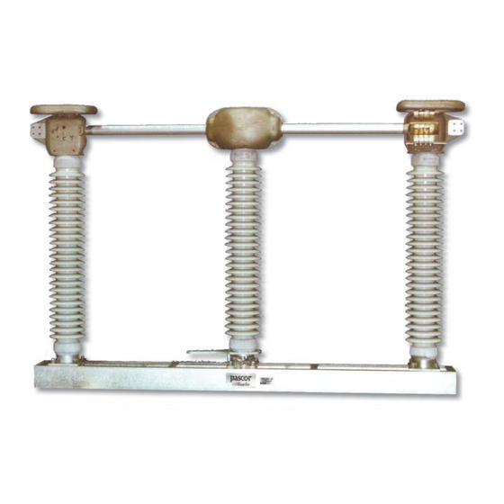
Summary of Contents for PASCOR ATLANTIC TTT7
- Page 1 IB-TTT7 May 2012...
- Page 2 Contents Subject Page Receiving and Handling ..........Installation and Adjustment Step 1.
- Page 3 IMPORTANT: Read manual before installing or maintaining equipment! Make absolutely sure that equipment is de-energized and properly grounded. This manual should be used in conjunction with the factory drawings. The drawings contain critical information, which if not followed could affect the operation of the switch. Instructions can not cover all possible variations in equipment nor provide for every possible contingency to be met in connection with installation, operation or maintenance.
- Page 4 Step 3 —Mounting Operating Bearing Step 5 — Mounting Current Carrying Parts Mount the operating bearing and its supporting Rotate the center insulator column to the open base on the supporting structure as shown on the position as shown on the drawings. The stop at the control drawing.
- Page 5 contacts on the ends of the blade should approach 6—3 Blade Engagement When Switch is Closed the jaw fingers at the same time and the blade Due to varying friction and deflection, the distance should hit both stops at about the same time. Also between the blade and its stop (dimension H in Fig.
- Page 6 Fig. 5 Worm Gear Operator Step 9—Installing Operating Mechanism Either a swing handle or a worm gear mechanism is (normally) supplied for manual switch operation. Swing Handle Operator To install the swing handle operator: With ground strap in place on vertical operating pipe, slide handle and handle lock plate over the end of the vertical operating pipe.
- Page 7 P a g e...
- Page 8 within the tolerances described previously. The Worm Gear Mechanism With ground strap in place on vertical operating stop at each switch base and the stop for the pipe, slide worm gear mechanism (Fig. 5) over the operating bearing should be touching, or nearly vertical operating pipe and attach it to the so.
- Page 9 Notice: In cases where a copper conductor is used, bolt a tinned terminal clamp (if available) to the aluminum switch terminal pad. If a non-tinned Table 1 terminal clamp is used, apply a liberal amount of Lubrication Guide for Outdoor Switch Components electrical joint grease at the joint and all over the Qty.
- Page 10 RENEWAL PARTS Refer to the switch nameplate when ordering renewal parts. The nameplate is attached to the base assembly of each switch pole. The same data is shown on the record engineering drawings. The master file at the factory is linked to the serial number on the nameplate.

Need help?
Do you have a question about the TTT7 and is the answer not in the manual?
Questions and answers
The grease that is on a 345kv switch need to stay applied. In blowing sand and dirt condition is there a different mothed?