
Related Manuals for Jefferson JEFSWMIT12-110


Summary of Contents for Jefferson JEFSWMIT12-110
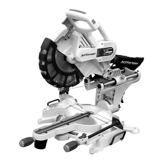
- Page 1 SLIDING COMPOUND 305mm MITRE SAW 2000W • GEAR DRIVEN MOTOR • LASER GUIDE • DOUBLE BEVEL JEFSWMIT12-110 JEFSWMIT12-230 User Manual v.1.2...
-
Page 3: Table Of Contents
USER MANUAL V1.2 JEFSWMIT12-110 • JEFSWMIT12-230 305mm SLIDING COMPOUND MITRE SAW 1. Contents 1. Contents 2. Technical Specification & Cutting Capacity 3. Safety Information 4. Unpacking & assembly 5. Adjustments 6. Cutting Operations 7. Replacing / Installing a Blade 8. Maintenance... - Page 4 USER MANUAL V1.2 JEFSWMIT12-110 • JEFSWMIT12-230 305mm SLIDING COMPOUND MITRE SAW 2. Technical Specification RATED SUPPLY VOLTAGE: 230V (13A) / 110V (16A)* - 50Hz OUTPUT: 2000W (2.7HP) MOTOR TYPE: GEAR DRIVEN NO LOAD SPEED: 4500RPM BLADE DIAMETER: 12" / 305MM BLADE BORE: Ø...
-
Page 5: Safety Information
USER MANUAL V1.2 JEFSWMIT12-110 • JEFSWMIT12-230 305mm SLIDING COMPOUND MITRE SAW 3. Safety Information 3.1 General Safety 1. KNOW YOUR TOOL Read and understand the owners manual and labels affixed to the tool. Learn its application and limitations as well as its specific potential hazards. - Page 6 USER MANUAL V1.2 JEFSWMIT12-110 • JEFSWMIT12-230 305mm SLIDING COMPOUND MITRE SAW 3.2 Additional Safety Instructions for Sliding Compound Mitre Saw Blades 1. Use only cross-cutting saw blades. When using carbide tipped blades, do not use blades with deep guillets as they can deflect and contact guard.
- Page 7 USER MANUAL V1.2 JEFSWMIT12-110 • JEFSWMIT12-230 305mm SLIDING COMPOUND MITRE SAW 3.3 Electrical Safety Information All electrical connections must be done by a qualified electrician. Failure to comply may result in serious injury! • All adjustments or repairs must be done with the miter saw disconnected from the power source.
- Page 8 USER MANUAL V1.2 JEFSWMIT12-110 • JEFSWMIT12-230 305mm SLIDING COMPOUND MITRE SAW 3.4 Working Environment • Keep the work area clean. Cluttered workbenches increase the risk of accidents and injuries. • Do not expose the tool to water or any other liquid. Do not use power tools in damp or wet areas. Do not expose power tools to rain.
-
Page 9: Unpacking & Assembly
USER MANUAL V1.2 JEFSWMIT12-110 • JEFSWMIT12-230 305mm SLIDING COMPOUND MITRE SAW 3.5 General Safety Warnings for your Laser 1. WARNING : Read all safety warnings and all instructions. Failure to follow the warnings and instructions may result in serious injury. -
Page 10: Adjustments
USER MANUAL V1.2 JEFSWMIT12-110 • JEFSWMIT12-230 305mm SLIDING COMPOUND MITRE SAW WARNING! Before making any cut, make sure the mitre lock handle is fully tightened. Preset Mitre Locks There are preset mitre stops at 0˚, 15˚, 22.5˚, 30˚ and 45˚ to the left and right. - Page 11 USER MANUAL V1.2 JEFSWMIT12-110 • JEFSWMIT12-230 305mm SLIDING COMPOUND MITRE SAW Depth Of Cut Stop Adjustment In its normal position, the depth of cut stop Fig.7 permits the saw blade to cut right through a workpiece. When the saw arm is lifted, the depth of cut stop (A) Fig.7 can be slid over towards the front of the saw so that the depth adjustment screw (B) contacts the stop as the saw head is lowered.
- Page 12 USER MANUAL V1.2 JEFSWMIT12-110 • JEFSWMIT12-230 305mm SLIDING COMPOUND MITRE SAW Setting The Fence Square With The Blade 1. Make sure that the electrical plug is removed from the main power supply. 2. Push the saw head down to its lowest position, then pull and turn the head release knob to hold the saw head in the transport position.
-
Page 13: Cutting Operations
USER MANUAL V1.2 JEFSWMIT12-110 • JEFSWMIT12-230 305mm SLIDING COMPOUND MITRE SAW 6. Cutting Operations Crosscutting When cutting a piece of wood it is not always necessary to use the slide mechanism. In these cases make sure that the slide lock knob (A) Fig.16 is locked to prevent the saw arm from sliding. - Page 14 USER MANUAL V1.2 JEFSWMIT12-110 • JEFSWMIT12-230 305mm SLIDING COMPOUND MITRE SAW Bevel Cut A bevel cut is made by cutting across the grain of the workpiece with the blade angled to the fence and mitre table. The mitre table is set at the 0º position and the saw head is set at an angle between 0˚ and 45˚...
-
Page 15: Replacing / Installing A Blade
USER MANUAL V1.2 JEFSWMIT12-110 • JEFSWMIT12-230 305mm SLIDING COMPOUND MITRE SAW 7. Replacing / installing a Blade • WARNING: Never attempt to use a blade larger than the stated capacity of the saw (10”). It will come into contact with the blade guards and housing. -
Page 16: Maintenance
USER MANUAL V1.2 JEFSWMIT12-110 • JEFSWMIT12-230 305mm SLIDING COMPOUND MITRE SAW 8. Maintenance Note: All the ball bearings are sealed and lubricated for life and will require no maintenance. Cleaning • After each use, wipe off chips and dust adhering to the tool with a cloth. -
Page 17: Parts Identification
USER MANUAL V1.2 JEFSWMIT12-110 • JEFSWMIT12-230 305mm SLIDING COMPOUND MITRE SAW 9. Parts Identification... - Page 18 USER MANUAL V1.2 JEFSWMIT12-110 • JEFSWMIT12-230 305mm SLIDING COMPOUND MITRE SAW Name Quantity Name Quantity Name Quantity Screw Rubber boot Pivot shaft Spring washer Motor housing Steel wire baffle ring Washer Screw Bracket Belt cover Brush hold Linear bearing Socket head screw...
- Page 19 USER MANUAL V1.2 JEFSWMIT12-110 • JEFSWMIT12-230 305mm SLIDING COMPOUND MITRE SAW Name Quantity Name Quantity Turntable bolt Lock handle cap Turntable bolt cover Screw Screw Lock handle Knob(long) Fixture Safety foot Locked nut Lock boot Roled pin Lock bolt Lock bolt...
- Page 20 Jefferson will assume both the parts and labour expense of correcting defects during the stated warranty periods below. All warranty periods start from the date of purchase from an authorised Jefferson dealer. If proof of purchase is unavailable from the end user, then the date of purchase will be deemed to be 3 months after the initial sale to the distributor.
- Page 21 • A Warranty Returns form will be sent to you for completion and return by post or fax, together with details of your nearest authorised Jefferson repair centre. On receipt of this form Jefferson will arrange to collect the equipment from you at the earliest convenience.
- Page 22 USER MANUAL V1.2 JEFSWMIT12-110 • JEFSWMIT12-230 305mm SLIDING COMPOUND MITRE SAW NOTES...
- Page 24 Before attempting to use this product please read all the safety precautions and operating instructions outlined in this manual to reduce the risk of fire, electric shock or personal injury. Jefferson Tools, Herons Way, Chester Business Park, Chester, United Kingdom, CH4 9QR Tel.
Need help?
Do you have a question about the JEFSWMIT12-110 and is the answer not in the manual?
Questions and answers