Advertisement
Table of Contents
- 1 Table of Contents
- 2 Important Safety Information
- 3 Technical Specifications
- 4 Before Installation
- 5 Installation Instruction
- 6 4A44A. Flush Mounted Installation
- 7 Wall-Mounted Installation
- 8 5A. Manual Control Panel
- 9 5B. Remote Control
- 10 Care and Maintenance
- 11 Limited Warranty
- 12 Troubleshooting Guide
- Download this manual
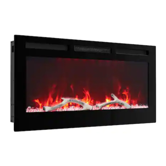
In Wall Recessed Electric Fireplace
Model Number:ZHX-36-027, ZHX-36-028,
WARNING
CAUTION
DO NOT RETURN!
Contact our customer service team for help first.
Customer Service Center: 800-385-0608 or aftersales@cye-way.com
USER MANUAL
ZHX-36-029, ZHX-42-034,
ZHX-42-035,
120V AC / 60Hz / 1500W
Read and understand this entire user manual, including all
safety information, before plugging in or using this product.
Failure to do so could result in fire, electric shock, or serious
personal injury.
Keep this user manual for future reference. If you sell or
give this product away, make sure this manual
accompanies this product.
Two people are required to lift this item. It is heavy and will
break if dropped.
Advertisement
Table of Contents

Subscribe to Our Youtube Channel
Related Manuals for Home Depot ZHX-36-027


Summary of Contents for Home Depot ZHX-36-027
- Page 1 In Wall Recessed Electric Fireplace USER MANUAL Model Number:ZHX-36-027, ZHX-36-028, ZHX-36-029, ZHX-42-034, ZHX-42-035, 120V AC / 60Hz / 1500W Read and understand this entire user manual, including all safety information, before plugging in or using this product. Failure to do so could result in fire, electric shock, or serious WARNING personal injury.
-
Page 3: Table Of Contents
CONTENT 1. Important Safety Information................2 2. Technical Specifications …………………………………….……..….……3 3. Before Installation …………..………………………………………..….……4 4. Installation Instruction ……………………………..…………....……...…6 ….…………………..…………....……...…6 4A44A. Flush Mounted Installation …...…………………..…………....……...…7 4B. Wall-mounted installation 5. Operation Instruction ………………………..……..….………………....…14 5a. Manual Control Panel ……………………………....…..…..….15 5b. Remote Control ……………………………………….......…..17 6. Care and Maintenance ……………………………………..….....19 7. -
Page 4: Important Safety Information
1.IMPORTANT SAFETY INFORMATION WARNING: Any use of this appliance other than that recommended by the manufacturer in this owners manual may cause fire, burns, electric shock and/or other serious injuries or death. When using electrical appliance, basic precautions should always be followed to avoid the risk of fire, electric shock and injury to persons including the following: Read all instructions before using this appliance. -
Page 5: Technical Specifications
2.TECHNICAL SPECIFICATIONS 2.1) Electric Specifications Model Size Volt Watt(min/max) BTU(max) ZHX-36-027 36IN ZHX-36-028 42IN ZHX-36-029 50IN 1500 5120 12.5 ZHX-42-034 60IN ZHX-42-035 72IN 2.2) Product Dimensions Overall Size View Size Firebox Dimension Model Unit Inch 31 1/4 10 3/4 33 5/8... -
Page 6: Before Installation
Overall Size View Size Firebox Dimension Model Unit Inch 55 1/4 10 3/4 57 5/8 4 5/16 ZHX-42-034 60IN 1524 1404 1464 Inch 67 1/4 10 3/4 69 5/8 4 5/16 ZHX-42-035 72IN 1828 1708 1768 Note: E is the width of the firebox only. Note: Installation dimensions please see Installation Instruction. - Page 7 A.Firebox (1pc) B.Glass Panel (1pc) C.Remote Control(1pc) D.Carbon Bed (1pc) E. Fixing Bracket H.Log (1pc) F. Fixing Bracket G.Faux Crystal (1 bag) not included parts 42” (1pc) (1pc) not included parts (1pc) 36” parts 60” and 72” 2pcs parts 72” 2pcs HARDWARE CONTENTS (shown actual size) CC: Bolt AA: Wall Anchor 4 PCS...
- Page 8 4. INSTALLATION INFORMATION Tools Required Phillips screwdriver, A small flat head screwdriver, lectric drill, A 1/4” e A pliers will be needed. Locating the Appliance Your new electric fireplace may be installed virtually anywhere in your home. However, when choosing a location, ensure that the general instructions for safety are followed.
-
Page 9: 4A44A. Flush Mounted Installation
The flush mounted height is reserved 16-1/4"(413mm), The flush mounted depth is reserved 4-1/2"(114mm), The flush mounted length A1 is reserved as follows: Model 36" 42" 50" 60" 72" ZHX-36-027 ZHX-36-028 ZHX-36-029 ZHX-42-034 ZHX-42-035 Inch 33.94 39.92 47.95 57.95 69.92 1014... - Page 10 4.A3) Fix the fixing brackets at both sides by 6pcs Bolt (CC) as shown. Note:The hook hole of the fixing bracket is front. Spare Parts E. Fixing Bracket F. Fixing Bracket Hardware Used CC: Bolt 6PCS 4.A4) Insert the firebox into the opening, adjust the position of unit and Centered.
- Page 11 4.A7) Please put Carbon Bed(D) into the furnace electric firebox (A) horizontally, the Carbon Bed(D) not distinguished between the front and the back. Spare Parts D: Carbon Bed 4.A8) Depending on your preference,place faux crystals (G) or log (H.I.J.K) into the base of electric firebox (A).
-
Page 12: Wall-Mounted Installation
4.A10) Fix the glass front by screws (CC) and complete the installation. Screws (CC) reference model configuration. Hardware Used CC: Bolt 36"/ZHX-36-027 2PCS CC: Bolt 42"/ZHX-36-028 2PCS CC: Bolt 50"/ZHX-36-029... - Page 13 Model 36” 42” 50” 60” 72” Overall Size ZHX-36-027 ZHX-36-028 ZHX-36-029 ZHX-42-034 ZHX-42-035 Inch 34-13/32” 40-25/64” 48-27/64” 58-27/64” 70-25/64” 1026 1230 1484 1788 Inch 5-5/16” 5-5/16” 5-5/16” 5-5/16” 5-5/16” 4.B2) Fix the fixing brackets at both sides by 6pcs Bolt (CC) as shown.
- Page 14 4B.4) With the help of another person, lift the fire box(A) and hang up the fire box onto the wall with the screw(BB). Note:Do not fasten the screws tightly. Leave 1/4” (6mm) spacing. 4B.5~10) The subsequent steps are Flush Mounted Installation same, Refer to step 4A.6~4A.11 of page 8~10.
- Page 15 Remove the 2pcs screws to release the Pull the junction box out. Press the screwdriver, cover of junction box. pull the wire out at the mean time to release the wires of power cord. Use a pliers to take the wire clip off and move Insert the hard wires through the BIG hole of the away the power cord.
- Page 16 5. OPERATING INSTRUCTIONS Electrical Supply Circuit Requirements Plan the location of the appliance so that it will have adequate electric power. A 15 AMP, 60Hz circuit is required for 120V installation. The appliance should ideally be located close to a suitable main socket to enable power connection. ...
-
Page 17: 5A. Manual Control Panel
5A. Manual Control Panel Use the control panel: (located in the electric fire box right side) 5a.A) Power: Push button to turn ON or turn OFF. It is invalid to child lock state. The POWER button supplies power to all the features of the electric insert. This button must be ON for any of the features to work properly. - Page 18 Display Carbon color White Amber Green A Green B Green C Green D Blue A Display Carbon color Blue B Blue C Violet A Violet B Violet C Polar Spot Light: 5a.D) Press to Activate the back spot light function,the system will set the spot light, the digital Blue display screen will be shown 08.
-
Page 19: 5B. Remote Control
5a.H) Display Screen: The Digital Display Screen will display the corresponding numbers of Flame,Carbon Light,Spot Light,Heater,Timer,Child Lock. 5B. Remote Control The remote control can be used up to 13 feet (4 meters) away from the heater, so long as there are no obstructions between the remote control and the heater. - Page 20 Warning: Changes or modifications to this unit not expressly approved by the party responsible for compliance could void the user’s authority to operate the equipment. This device complies with Part 15 of the FCC Rules. Operation is subject to the following two conditions: (1) This device may not cause harmful interference, and (2) this device must accept any interference received, including interference that may cause undesired operation.
-
Page 21: Care And Maintenance
6. CARE AND MAINTENANCE ALWAYS turn the appliance OFF and unplug the power cord from the outlet before cleaning, performing maintenance, or moving this fireplace. Failure to do so could result in electric shock, fire, or personal injury. NEVER immerse in water or spray with water. Doing so could result in ... -
Page 22: Limited Warranty
7. LIMITED WARRANTY This warrants to the original purchaser that this product is free from defects in material and workmanship as of the date of purchase and that it will, under normal use and proper care, remain so for one year from the date of purchase. Missing or initially defective parts will be replaced free of charge during the period of this limited warranty. - Page 23 b. If not, unplug the unit and recheck next day to see if it can work properly. c. If still not, the fan assembly need to be checked and please contact service team for a checking instruction. 2) Product has been used for some time: a.
- Page 24 Thank you for purchasing this product! If you have questions about assembly or operation of this product, or missing parts, or if the product is damaged, please E-mail us at: aftersales@cye-way.com Or call 800-385-0608 - 22 -...
Need help?
Do you have a question about the ZHX-36-027 and is the answer not in the manual?
Questions and answers