
Related Manuals for SIRE XROOM

Summary of Contents for SIRE XROOM
- Page 1 OPERATING AND INSTALLATION MANUAL RECOVERY AND HEATING UNIT XROOM Version 1 – GBR(23/06/2021) D-502-0152...
-
Page 2: Table Of Contents
1.1................................. 5 Introduction 1.2. Warnings and Symbols ................................... 5 1.3.1. Unit Designation ..................................... 6 1.3.2. Prohibited environment, use, installation of Xroom: ..........................6 1.4.......................7 Transport, Delivery Control, and Storage 1.4.1. Transport ........................................ 7 1.4.2. Delivery Inspection....................................7 1.4.3. - Page 3 Technical data of water heaters................................16 2.3.4. Heat and moisture recovery efficiency ..............................17 Unit Installation ..................................18 General information, recommendations, and safety when installing the Xroom units..........18 3.1. Electrical safety before installation of the unit............................ 18 3.1.1. Unpacking ......................................18 3.1.2.
- Page 4 Removal of a filter ................................43 6.2. Filter Inserting ................................. 44 6.3. Reset filter countdown ..............................44 Regular Maintenance and Cleaning of Xroom Units....................... 45 7.1. Visual Inspection of the Unit Casing ................................. 45 7.1.1. Visual Inspection and Cleaning of the Heat Exchanger ............................ 45 7.1.2.
-
Page 5: General Information
1. General information Introduction This document “Operating and Installation Manual” is intended for decentralised Xroom recovery units (hereinafter referred to as the “Unit”) with a possible combination of water or electrical heating – 2in1. At the same time, it is superior to the brief manual placed directly on the unit, the so-called “Quick Manual”. -
Page 6: Unit Designation
The unit can be used in spaces with the maximum nominal flow requirement: o 100 m3/h – Xroom 100 – regular residential premises, smaller offices, hotel rooms, etc. o 250 m3/h – Xroom 250 – larger office facilities, school classrooms, hospital rooms, etc. -
Page 7: Transport, Delivery Control, And Storage
0 °C, it must be put into the working environment where it will be installed for at least 2 hours after unpacking. 1.5. Contents of the Package 1.5.1. Xroom 100 (XR1-010-EC…) Box 1 – Xroom unit Xroom unit body with front metal cover 1 pc installation template with assembly pins 1 pc bolt M6x25... -
Page 8: Xroom 250 (Xr1-025-Ec
1.5.2. Xroom 250 (XR1-025-EC…) Box 1 – Xroom unit Xroom unit body with front metal cover 1 pc installation template with mounting pins 1 pc bolt M6x25 5 pc bolt M6x20 with a plastic head 3 pc Quick manual + safety data sheet... -
Page 9: Technical Parameters
2. Technical Parameters Design of the Xroom unit Fig. 1 Version 1 – GBR(23/06/2021) D-502-0152... - Page 10 Fig. 2 Version 1 – GBR(23/06/2021) D-502-0152...
-
Page 11: Front Metal Cover (Position 1)
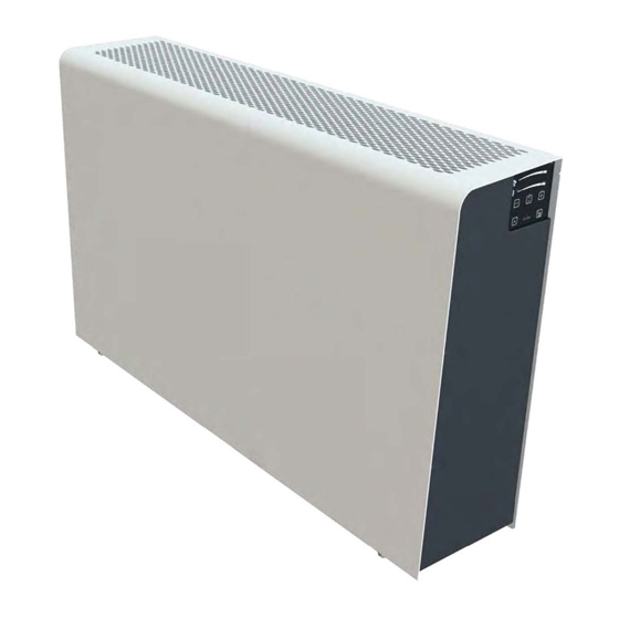
Fig. 3 2.1.1. Front metal cover (position 1) Metal cover made of aluminium sheet, thickness 2 mm with powder paint against corrosion. Standard version in two shades RAL 9003 (white), RAL 7016 (anthracite) 2.1.2. Installation template (position 2) - aluminium sheet construction, thickness 2 mm treated with powder paint against corrosion. Standard version in two shades RAL 9003 (white), RAL 7016 (anthracite). -
Page 12: Filters (Position 8)
2.1.8. Filters (position 8) M5 filters (ISO COARSE 70%) are included in the delivery. F7 filters (ISO ePM1 60%) can be supplied upon request. Evaluation of filters per ČSN EN ISO 16890. 2.1.9. Filter caps (position9) Filter caps are used to seal the filters in the unit cover. They are made of black pressed EPP plastic (expanded polypropylene). -
Page 13: Main Dimensions Of The Xroom Unit
2.2. Main dimensions of the Xroom unit 2.2.1. Xroom-100 (XR1-010-EC...) Fig. 3 Fig. 3 2.2.2. Xroom-250 (XR1-025-EC…) Fig. 4 Version 1 – GBR(23/06/2021) D-502-0152... -
Page 14: Technical Parameters Of Xroom Units
Technical parameters of Xroom units Basic technical parameters Basic technical parameters – Xroom-100 (XR1-010-ECxxHR...) – heat exchanger Line XR1-010-ECS0HRX… XR1-010-ECV1HRX… XR1-010-ECE1HRX… XR1-010-ECS0HRP… XR1-010-ECV1HRP… XR1-010-ECE1HRP… Type of recovery exchanger HRV with temperature efficiency pre-heater electric electric electric Unit equipment after heater... -
Page 15: Acoustic Data
**** unit weight, without water and packaging EC Declaration of Conformity – the current and full version of the EC Declaration of Conformity can be found on our website www.xvent.cz in the “Download Documents” section for the Xroom product 2.3.2. Acoustic Data XR1-010-EC... -
Page 16: Technical Data Of Water Heaters
Tab 9 Accessibility of exterior sound 2.3.3. Technical data of water heaters XR1-01-ECV1HR... (heat recovery exchanger) Tab 10 XR1-010-ECV1ER... (enthalpy recovery exchanger) Tab 11 XR1-025-ECV1HR... (heat recovery exchanger) Tab 12 Version 1 – GBR(23/06/2021) D-502-0152... -
Page 17: Heat And Moisture Recovery Efficiency
XR1-025-ECV1ER... (enthalpy recovery exchanger) Tab 13 2.3.4. Heat and moisture recovery efficiency Tab. 14 XR1-010-EC… Version 1 – GBR(23/06/2021) D-502-0152... -
Page 18: Unit Installation
Tab 15 XR1-025-EC… 3. Unit Installation General information, recommendations, and safety when installing the Xroom units Electrical safety before installation of the unit Before starting any installation work, make sure that the wiring box or mains socket that you want to use to connect the unit is equipped with a protective (green-yellow) wire or contact (pin). - Page 19 Fig. 5 Version 1 – GBR(23/06/2021) D-502-0152...
-
Page 20: Unpacking Installation - Box 2
Unpacking Installation – Box 2 3.1.2.2. Unpacking of the installation accessories is carried out gradually, according to the installation work course, as specified in this manual: Fig. 6 Package Content Description – Box 2 A) Plastic white tube 125 mm (XR1-010-DUCT-1) or 150 mm (XR1-025-DUCT-1), length 500 mm Ø... -
Page 21: Unit Location
3.1.3. Unit Location The unit is installed on the interior side of the external perimeter wall of a ventilated room. The usual location for the unit is under the window. Consider placing the unit in the interior away from the surrounding objects with respect to the recommended distances from the unit (e.g., filter replacements, servicing) specified in Section 3.1.4. -
Page 22: Installation Positions Of The Xroom Unit
3.1.5. Installation Positions of the Xroom Unit All the Xroom unit types can be installed in the following position: Fig. 8 Fig. Any other position is prohibited Xroom Unit Installation The unit must be operated in enclosed and dry areas with room temperature ranging between +5 °C and +30 °C. -
Page 23: Fitting And Mounting The Installation Template With Mounting Pins
If you carry out the installation into the wall with a thickness greater than 500 mm, get also the material: o Plastic air-conditioning piping with a length greater than the wall thickness: Xroom 100 (XR1-010...) piping diameter 125 mm 2 pc ... -
Page 24: Preparation Of Piping Holes In The Existing Wall
Use the appropriate technology (core drilling) to drill holes into the wall or approach a specialised company that performs this service professionally. Core drill (drilled hole) diameter: o Xroom 100 (XR1-010…) 152 mm (hole in installation template 155 mm) Ø... -
Page 25: Preparation Of Supply And Drain Piping
If necessary, use the marks on the installation template to determine the centre of the holes BE SURE TO KEEP THE CORE DRILL – DRILL AXIS 90° WITH WALL!!! HOLE CENTRE Fig. 12 It is essential that the axis of the drilled hole is horizontal and 90° to the inner surface of the circumferential wall. -
Page 26: Extension Of Piping For Walls With A Thickness Greater Than 500 Mm
If there is a need for longer piping (plastic HVAC piping), contact your nearest HVAC seller. You will need: o plastic HVAC piping (2 pcs) with a length greater than the thickness of the wall, on which the unit will be installed with a diameter of: Xroom 100 (XR1-010…) 125 mm ... -
Page 27: Installation Of The Supply And Drainage Piping On The Unit
3.2.5. Installation of the Supply and Drainage Piping on the unit Move box 1 - the “Xroom unit” back to the assembly area and open it. Do not unpack the unit from the box. Remove the plastic bag with connecting material from the box (M6x30 bolts, M6x20 bolt with plastic head) and store it for later use. -
Page 28: Gluing Insulating Pads
2 cm Fig. 16 Cut the box on the shorter side of the installed piping for better access to the self-tapping locking bolts. installed piping for better access to the self-tapping Secure the installed piping with self-tapping bolts 4 x 22 mm (part of the mandatory accessories delivery Ø... -
Page 29: Installation Of The Xroom Unit On The Wall
Close box 1 – “Xroom unit” with the front metal cover and place it in a safe place outside the assembly and place it in safe place the assembly area to prevent damage or dusting of the front cover. -
Page 30: Water Heater Variant(Xr1-Xxx-Ecv1
ATTACH THE UNIT TO THE INSTALLATION PINS USING M6x25 A BOLTS TIGHTEN WITH APPROPRIATE STRENGTH – MAX 5 Nm Fig. 20 Pay special attention to the proper installation of the tubes into the prepared holes in the wall to avoid damaging them. -
Page 31: Securing, Insulating Piping In The Wall
After connecting the water exchanger to the heating system, fit the rear wall of the unit to the installation template and secure the unit with 5 M6x25 bolts (part of the delivery, in a bag) to the installation pins. Fig. 22 Pay special attention to the proper installation of the tubes into the prepared holes in the wall to avoid damaging them. -
Page 32: Fitting The Piping On The Outer Side Of The Wall With Outlet
Xroom 250 size – 3 pc Remove the front cover of the unit from box 1 – "Xroom unit". Hook the unit cover behind the unit body and, at the same time, attach it to the partially bolted M6x20 bolts with plastic head. -
Page 33: Electrical Installation - Connection To Mains
ATTACH THE FRONT COVER, TIGHTEN THE BOLTS BY HAND – ALIGNING THE COVER WITH THE TEMPLATE Fig. 25 Fig. - Tighten the plastic head bolts with adequate force to prevent their damage or damage to the nuts in the their damage damage the nuts unit body. -
Page 34: Connection Of The Unit To The Wiring Box
Connection – installation of a plug on the supply cable must be performed by a qualified person who has a valid authorisation for this activity and knowledge of the relevant standards and directives in the given country. 3.3.2.3. Recommended Xroom UnitProtection Tab.16 3.3.3. Display of electrical parameters all the unit's electrical parameters are provided on the serial plate Fig. -
Page 35: Regulation
It is therefore ready for immediate use after installation on the wall. Electrical Accessories to the Xroom Unit Before connecting electrical accessories, always switch off the unit on the controller and with the main switch (position 18). -
Page 36: Radon Sensor Connection - Aqs Radon
Radon sensor Jumper for switching the logic of the NC and NO switching Limit contact EXT1 Fig. 29 4.2.2. Radon Sensor Connection – AQS RADON A radon sensor may be connected to the unit to measure the content of radon concentration in the air at the unit installation site. -
Page 37: Technical Parameters Of External Contact
o Using a remote switch. In the facility, the electrical appliances are switched off by one button (the total stop system). The unit may be included in this system via this contact. o Using a time relay. The unit may be switched on/off by a time relay located in the switchboard. Technical Parameters of External Contact o Switching voltage 24 VDC / 5 mA. -
Page 38: Commissioning
5. Commissioning Prior to first startup, check: that all the installation work has been duly completed as indicated in Section 3, whether the power supply cable of the unit is properly connected to the mains, whether the front metal cover of the unit (position 1) is properly tightened with M6x20 bolts with a plastic head. -
Page 39: Control Mode - 1 Click
The display is lit for approx. 4 sec., then the controller returns to the sleep mode. The functions that can be started from this mode are listed in Table 17. Description of the control functions of the Xroom units. 5.3.3. Unit Setting Mode – 2 clicks The setting or activation of some functions is only possible from this mode. -
Page 40: Description Of The Functions Of The Buttons And Regulation
5.4.2. Description of the functions of the buttons and regulation Tab 17 Version 1 – GBR(23/06/2021) D-502-0152... -
Page 41: Description Of The Ventilation Power Setting Range
5.4.3. Description of the ventilation power setting range Tab 18 Setting the correct performance of the unit Tab 19 Ventilation Power Settings 1. In regular mode, double-click on button 1 or 2 or 3 to enter the settings mode – LED 10 flashes (fan pictogram). -
Page 42: Hidden Regulation Functions
Fig. 36 Fig. 36 5.4.8. Hidden Regulation Functions The control behaviour includes automatic processes that ensure optimal operation of the unit with emphasis on the maximum service life and efficiency of the operation. These processes are part of the manufacturer's factory setup and know-how. The user cannot change them. As a result of these automatic processes, the behaviour of the unit may be different from that assumed by the user. -
Page 43: Replacing Filters
6. Replacing Filters The unit is equipped with a filter clogging countdown for approx. 6 months (approx. 4400 hours). The countdown reads the unit's real operation. Filter clogging depends on the environment, in which the unit operates. Especially, on the dustiness of the surrounding air –... -
Page 44: Filter Inserting
Filter Inserting Pay attention to the correct orientation of the filter before it is inserted into the unit with regard to the air flow Insert new filters into the unit. Align the filter holders so that they do not interfere with the installation of the plastic filter caps. Install the filter caps into the unit cover. -
Page 45: Regular Maintenance And Cleaning Of Xroom Units
7. Regular Maintenance and Cleaning of Xroom Units Before opening the unit during its maintenance and cleaning, the unit must be disconnected from the power supply Maintenance and cleaning must be performed at regular intervals; otherwise, the functionality of the unit may be impaired. -
Page 46: Visual Inspection Of The Supply Cable
- Never clean the heat exchanger with a damp cloth, as this could damage the unit or cause an electric shock (in the case of the version with the electric heat exchanger XR1-xxx-ECE1...) after restarting the unit. 7.1.2. Visual Inspection of the Supply Cable Visually check that the supply cable is not damaged, loosen, or torn from the connecting peripherals. -
Page 47: Visual Inspection - Cleaning Of Preheating, If Fitted With The Unit (Xr1-Xxx-Ecxxxxp
Vacuum dirt from the fan chamber and, if necessary, wipe it with a damp cloth with a common cleaning agent (e.g. soapy water). With extra care, vacuum dust from the fan assembly and, if necessary, wipe it with a damp cloth with a common cleaning agent (e.g. -
Page 48: Visual Inspection And Cleaning Of The Heat Recovery Exchanger
7.2.4. Visual Inspection and Cleaning of the Heat Recovery Exchanger Then, visually inspect and clean the heat recovery exchanger (position 12) Vacuum the heat exchanger. Beware of vacuuming around the heat recovery exchanger in the area of the air exhaust where the temperature sensor for anti-freeze protection is located in the heat exchanger. -
Page 49: Servicing
8. Servicing Warranty and non-warranty servicing may only be performed by a qualified professionally trained worker and only using original spare parts. The manufacturer reserves the right to make changes to the device that do not affect the essential properties of the device. 8.1. -
Page 50: Failure Persists
Failure persists Restart the unit – switch off the unit on the controller (button 2), switch off the unit using the main switch (position 18). Wait approx. 30 sec. and restart the unit. In the event of a persistent failure of the unit, do not attempt to repair the unit yourself. Switch the unit off using the main switch and disconnect it from the mains.
Need help?
Do you have a question about the XROOM and is the answer not in the manual?
Questions and answers