Sign In
Upload
Manuals
Brands
SIRE Manuals
Heating System
XROOM
SIRE XROOM Heating System Manuals
Manuals and User Guides for SIRE XROOM Heating System. We have
1
SIRE XROOM Heating System manual available for free PDF download: Operating And Installation Manual
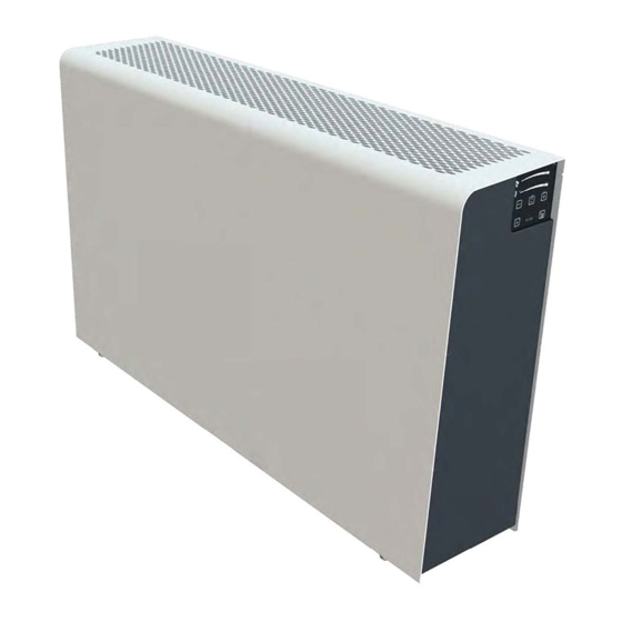
SIRE XROOM Operating And Installation Manual (50 pages)
Brand:
SIRE
| Category:
Heating System
| Size: 2 MB
Table of Contents
Table of Contents
2
General Information
5
Introduction
5
Warnings and Symbols
5
Unit Designation
6
Prohibited Environment, Use, Installation of Xroom
6
Transport, Delivery Control, and Storage
7
Transport
7
Delivery Inspection
7
Storage
7
Contents of the Package
7
Xroom 100 (XR1-010-EC
7
Xroom 250 (XR1-025-EC
8
Before Commencing the Installation
8
Technical Parameters
9
Design of the Xroom Unit
9
Front Metal Cover (Position 1)
11
Installation Template (Position 2)
11
Mounting Pins (Position 3)
11
Unit Body - Fitting (Position 4)
11
Unit Cover (Position5)
11
Reinforcement (Position 6)
11
Bolt M6X30 (Position 7)
11
Filters (Position 8)
12
Filter Caps (Position9)
12
Preheating (Position10)
12
Fans (Position11)
12
Recuperator (Position12)
12
Electric Heat Exchanger (Position 13)
12
Controller (Position14)
12
Regulator Box (Position15)
12
FILTER RESET Button (Position16)
12
Limit Switch (Position17)
12
Main Dimensions of the Xroom Unit
13
Xroom-100 (XR1-010-EC
13
Xroom-250 (XR1-025-EC
13
Technical Parameters of Xroom Units
14
Basic Technical Parameters
14
Acoustic Data
15
Technical Data of Water Heaters
16
Heat and Moisture Recovery Efficiency
17
Unit Installation
18
General Information, Recommendations, and Safety When Installing the Xroom Units
18
Electrical Safety before Installation of the Unit
18
Unpacking
18
Unpacking the Xroom Unit - Box 1
18
Unpacking Installation - Box 2
20
Unit Location
21
Location During the Buildingreconstruction
21
Location and Operation of the Unit in the Area with a Furnace (Fireplace)
21
Unit Location and Operation in the Area with an Air Conditioningunit
21
Minimum Installation Distances
21
Installation Positions of the Xroom Unit
22
Xroom Unit Installation
22
Installation Components Required for Installation of the Xroom Unit
22
Fitting and Mounting the Installation Template with Mounting Pins
23
Fitting the Installation Template on the Wall When Using the Construction Module
23
Fitting the Installation Template on the Existing Wall
23
Installation Template Mounting
23
Preparation of Piping Holes in the Existing Wall
24
Preparation of Supply and Drain Piping
25
Extension of Piping for Walls with a Thickness Greater than 500 MM
26
Extension of the Supply Piping with a Damper Assembly
26
Drain Piping Extension - White Plastic Tubes
26
Installation of the Supply and Drainage Piping on the Unit
27
Gluing Insulating Pads
28
Installation of the Xroom Unit on the Wall
29
Xroom Unit Final Fitting
29
Electric Heater Variant (XR1-010-ECE1
29
Water Heater Variant(XR1-XXX-ECV1
30
Securing, Insulating Piping in the Wall
31
Fitting the Piping on the Outer Side of the Wall with Outlet
32
Installation of the Front Metal Cover
32
Electrical Installation - Connection to Mains
33
General Information - Safety
33
Connection to Mains
33
Connection of the Unit to the Wiring Box
34
Connecting the Unit to the Electrical Outlet
34
Recommended Xroom Unitprotection
34
Display of Electrical Parameters
34
Regulation
35
General Information - Safety
35
Electrical Accessories to the Xroom Unit
35
Connecting Electrical Accessories
35
Radon Sensor Connection - AQS RADON
36
Technical Parameters of the Sensor for Connection to the Unit
36
Functionality of the Unit after Connecting the Radon Sensor
36
External Contact Connection - EXT 1
36
Technical Parameters of External Contact
37
Functionality of the Unit When Controlled by External Contact EXT1
37
Wiring Block Diagram
37
Commissioning
38
Prior to First Startup, Check
38
Activation - Basic Unitcommissioning
38
Controller Operating Modes
38
Sleep Mode - Regular Operating Mode
38
Control Mode - 1 Click
39
Unit Setting Mode - 2 Clicks
39
Unit Control
39
Control Panel - Controllers
39
Description of the Functions of the Buttons and Regulation
40
Description of the Ventilation Power Setting Range
41
Ventilation Power Settings
41
Temperature Setting Range - Only in the Electric Version (XR1-XXX-ECE1
41
Setting the Required Temperature
41
Display of the Indicated Statuses on the Controller by Leds
41
Hidden Regulation Functions
42
Automatic Unit Control Using AQS Sensors
42
Replacing Filters
43
Removal of a Filter
43
Filter Inserting
44
Reset Filter Countdown
44
Regular Maintenance and Cleaning of Xroom Units
45
Visual Inspection of the Unit Casing
45
Visual Inspection and Cleaning of the Heat Exchanger
45
Visual Inspection of the Supply Cable
46
Inspection - Cleaning of the Inner Area of the Unit - Disassembly
46
Cleaning the Fan Chamber and Fans
46
Visual Inspection - Cleaning of Preheating, if Fitted with the Unit (XR1-XXX-Ecxxxxp
47
Visual Inspection - Cleaning of Inlet and Drainage Piping
47
Visual Inspection and Cleaning of the Heat Recovery Exchanger
48
Re-Installation of Internal Components into the Unit
48
Servicing
49
Error Messages - Troubleshooting Procedure
49
Failure Persists
50
Final Decommissioning, Dismantling, and Disposal
50
Warranty
50
Advertisement
Advertisement
Related Products
SIRE OXeN X2-W-1.2-V
SIRE OXeN X2-N-1.2-V
SIRE OXeN X2-W-1.2-H
SIRE OXeN X2-N-1.2-H
SIRE OXeN X2-E-1.2-V
SIRE Xroom-100
SIRE Xroom-250
SIRE Categories
Musical Instrument
Heating System
More SIRE Manuals
Login
Sign In
OR
Sign in with Facebook
Sign in with Google
Upload manual
Upload from disk
Upload from URL