Table of Contents
Advertisement
Quick Links
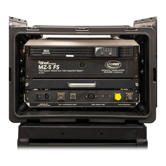
MZ-5 FS™ Inspection System
EM15201
Operation and Service Manual
®
Version 1.0 • December 2020
Copyright ©2020 InterTest Inc. All rights are reserved. No part of this publication may be reproduced,
stored in a retrieval system, or transmitted, in any form or by any means, electronic, mechanical,
photocopying, recording or otherwise, without the prior written permission of the publisher
Advertisement
Table of Contents

Subscribe to Our Youtube Channel
Related Manuals for InterTest iShot imaging MZ-5 FS

Summary of Contents for InterTest iShot imaging MZ-5 FS
- Page 1 ® Version 1.0 • December 2020 Copyright ©2020 InterTest Inc. All rights are reserved. No part of this publication may be reproduced, stored in a retrieval system, or transmitted, in any form or by any means, electronic, mechanical, photocopying, recording or otherwise, without the prior written permission of the publisher...
- Page 2 IMPORTANT: If you are in possession of a printed or electronic version of this document, be aware that it may not be the current version. To ensure that you are using the most up- to-date version of this document, please contact the InterTest Customer Service and Support Group.
-
Page 3: Table Of Contents
Table of Contents About This Manual ........................5 ◼ ..Disclaimer ..........................5 Purpose ..........................5 OSHA Compliance and Safety Guidelines ................... 5 ◼ ..Revision Information ........................6 ◼ ..Manual Versions ........................6 Cautionary Symbols and Symbol Terminology ................6 ◼... - Page 4 InterTest, Inc. • 908-496-8008 MZ-5 FS™ Inspection System Chapter 5 — Care and Maintenance ....................37 Chapter 6 — Components and Part Catalog ..................38 Chapter 7 — Service and Maintenance Records ................43 List of Figures Figure 1 Camera & Poles............................. 9 Figure 2 Camera Centering Rings ........................
-
Page 5: About This Manual
Equipment. Because this manual was designed for quick reference, it is restricted in scope to the operation of the system. Should you have questions beyond the scope of this manual, please call the InterTest Customer Support Group. -
Page 6: Revision Information
It is the responsibility of the technician or other service personnel to adhere to all OSHA guidelines as they concern PPE devices and their proper use. Revision Information As it becomes necessary to revise this manual, InterTest will give the reasons for the revision in this section. Revised Approved... -
Page 7: Safety Considerations
Never remove the top cover of the controller. Electrical shock hazards exist due to high internal voltage. There are no user-serviceable parts inside the controller, except for fuses, which are accessible via the rear panel. Refer all service to the InterTest Customer Service and Support Group. -
Page 8: System Setup
InterTest, Inc. • 908-496-8008 MZ-5 FS™ Inspection System The unit should never come in direct contact with any voltage or current source. Damage to the equipment and/or electrical shock to the operator may result. The unit is equipped with a power supply mounted in the back of the equipment. It accepts a 3- wire grounding type plug only. -
Page 9: Camera & Poles Setup
InterTest, Inc. • 908-496-8008 MZ-5™ FS Inspection System Figure 1 Camera & Poles Camera & Poles Setup Install the appropriate Camera Centering Rings Figure 2 Camera Centering Rings EM15201 Rev A Page 9 Version 1.0 • Nov 2020... -
Page 10: Attach Camera Cable Clamp
InterTest, Inc. • 908-496-8008 MZ-5 FS™ Inspection System Attach Camera Cable Clamp Install the Camera Cable Clamp as Shown Figure 3 Camera Cable Clamp Install Pole Centering Rings & Cable Clamps Install as many rings & clips as needed Figure 4 Pole Centering Rings & Cable Clips... -
Page 11: Install Cable & Exit Pole Termination
InterTest, Inc. • 908-496-8008 MZ-5™ FS Inspection System Install Cable & Exit Pole Termination Install Exit Pole Termination on the Last Pole Used. See Figures 5-8 Note: Be sure to “twist” the cable, Figure 7, & hold as shown prior to closing clamp or threads may be damaged... -
Page 12: Figure 7 Exit Pole Termination Installation Step 3
InterTest, Inc. • 908-496-8008 MZ-5 FS™ Inspection System Figure 7 Exit Pole Termination Installation Step 3 Figure 8 Exit Pole Termination Installation Step 4 EM15201 Rev A Page 12 Version 1.0 • Nov 2020... -
Page 13: Setup Support Stands
InterTest, Inc. • 908-496-8008 MZ-5™ FS Inspection System Setup Support Stands Set up Support Stands. & adjust height as needed. Make sure stands are level with each other & wheels are locked. Figure 9 Support Stands Open the Control Unit (CCU) -
Page 14: Connect Camera, Monitor & Encoder
InterTest, Inc. • 908-496-8008 MZ-5 FS™ Inspection System Figure 11 Hanging of Covers Connect Camera, Monitor & Encoder Note: Portable monitor uses an special 3 prong adapter that plugs into the monitor Power & video Cable Figure 12 Connect Camera, Power & Monitor... -
Page 15: Connect Downtube Encoder (If Used)
InterTest, Inc. • 908-496-8008 MZ-5™ FS Inspection System Connect Downtube Encoder (If Used) Figure 13 Downtube Encoder Connect Downtube Encoder (If Used) Install in Tube & Tighten Clamping Screw Figure 14 Down Tube Encoder Mounting Open Storage Drawer Get Keyboard & Mouse Note: No need to open computer drawer unless accessing DVD drive. -
Page 16: Power On The System
InterTest, Inc. • 908-496-8008 MZ-5 FS™ Inspection System Figure 15 Keyboard & Mouse Power ON the System After connecting the Monitor. (Monitor on Wheels or Portable unit) Turn ON Keyboard & Mouse Turn ON Main Power Switch Turn ON the UPS Note: Computer is set to “Turn ON”... -
Page 17: Figure 17- Computer Start Screen & Docuview Program
InterTest, Inc. • 908-496-8008 MZ-5™ FS Inspection System 1) Double Click on the Docuview Program Icon Figure 17- Computer Start Screen & DocuView Program Refer to Figure 18 & 19 2) Click on the Settings Tab Figure 18 & then General Settings Figure 19 a. -
Page 18: Figure 18 Opening General Settings Tabs
InterTest, Inc. • 908-496-8008 MZ-5 FS™ Inspection System Figure 18 Opening General Settings Tabs Refer to Figure 19 Figure 19 Opening Admin Mode 1) Double Click on “Docuview 2) “Settings Login” will appear 3) Type in Password a. Secret (Case sensitive) -
Page 19: Figure 20 General Settings
InterTest, Inc. • 908-496-8008 MZ-5™ FS Inspection System Refer to Figure 20 Figure 20 General Settings Refer to Figure 21 Figure 21 Image & Video Capture File Type Refer to Figure 22 EM15201 Rev A Page 19 Version 1.0 • Nov 2020... -
Page 20: Figure 22 File Naming
InterTest, Inc. • 908-496-8008 MZ-5 FS™ Inspection System 3) Menus available in “General Settings” a. File Naming i. Date/Time ii. Ascending iii. Custom Preface iv. Combination of text & numbers. Will add four digits to the end of The filename... -
Page 21: Figure 24 Camera Control & Toggle Between Cameras
InterTest, Inc. • 908-496-8008 MZ-5™ FS Inspection System a. Camera Presets (Configured in Admin mode) i. Includes camera & lighting settings Note: Change view button used to switch cameras Figure 24 Camera Control & Toggle Between Cameras 6) Refer to Figure 25 Camera & Lighting Control a. -
Page 22: Figure 26 Camera Setup
InterTest, Inc. • 908-496-8008 MZ-5 FS™ Inspection System 7) Refer to Figure 26 for Camera Set Up Figure 26 Camera Setup Click on Unity Settings to open Zoom & Focus Controls (Front Camera is manual focus, side view is autofocus) a. -
Page 23: Figure 27 Osd & Grid Settings
InterTest, Inc. • 908-496-8008 MZ-5™ FS Inspection System Figure 27 OSD & Grid Settings Figure 28 Presets EM15201 Rev A Page 23 Version 1.0 • Nov 2020... -
Page 24: Figure 29 Forward & Aft Sideview Lighting
InterTest, Inc. • 908-496-8008 MZ-5 FS™ Inspection System Figure 29 Forward & Aft Sideview Lighting Figure 21 Forward & Aft Sideview Lighting Refer to Figure 27 OSD, On-Screen Display a. On-Screen Display b. Font Size, Color & Location c. User Entered On-Screen Text d. -
Page 25: Capture Controls
InterTest, Inc. • 908-496-8008 MZ-5™ FS Inspection System Capture Controls Figure 31 General Settings **Note: -Date /Time: Done in sequential order -Ascending: Done in sequential order, 0001, 0002 etc. -Custom preface: User defined text. Adds value at end so that sequential images can be told apart... -
Page 26: Figure 32 Image & Video Capture
InterTest, Inc. • 908-496-8008 MZ-5 FS™ Inspection System Video Record “Active” Figure 32 Image & Video Capture Camera Settings: Note: Defaults set at Factory. Click “Reset” to revert to factory defaults EM15201 Rev A Page 26 Version 1.0 • Nov 2020... -
Page 27: Measurement
InterTest, Inc. • 908-496-8008 MZ-5™ FS Inspection System Table C Camera Settings Recommended Menu Options Options Notes Setting General Settings Image Capture Format JPEG 1080 Resolution BITMAP 4K Resolution Video Record File Naming Date / Time Asecending Custom Preface Asending... -
Page 28: Figure 33 Reference Dimension
InterTest, Inc. • 908-496-8008 MZ-5 FS™ Inspection System To “SET” Select “Reference Length” ii) Select Units, mm or inches iii) Select “Click & Drag for Scale” & “Display Scale Line” iv) “Click” on the screen while holding down the left mouse button. A Pencil icon will appear. -
Page 29: Line
InterTest, Inc. • 908-496-8008 MZ-5™ FS Inspection System Line a) Place the 1 point. A Cross Hair will appear Hold down the Left mouse button & drag to the 2 point. Let go when you arrive at the second point. -
Page 30: Angle
InterTest, Inc. • 908-496-8008 MZ-5 FS™ Inspection System Angle a) You need to click on the screen three times to form the points of the angle Once the angle is placed. You can move the end points. Hover over the point. The cursor will change to an Arrow. -
Page 31: Circle
InterTest, Inc. • 908-496-8008 MZ-5™ FS Inspection System Circle a) Place the cross hair while holding the left mouse button down. A Circle will appear on the screen. ii) Move the mouse to change the size of the circle. iii) Of the two dots that appear with the circle. The center one allows you to move the circle. -
Page 32: Rectangle
InterTest, Inc. • 908-496-8008 MZ-5 FS™ Inspection System Rectangle a) Place the cross hair while holding the left mouse button down. A Rectangle will appear on the screen. ii) Move the cursor over a side of the rectangle. It will change to a double arrow . -
Page 33: Forward Camera Focus Adjustment
InterTest, Inc. • 908-496-8008 MZ-5™ FS Inspection System Forward Camera Focus Adjustment Figure 38 Forward Camera Focus Adjustment EM15201 Rev A Page 33 Version 1.0 • Nov 2020... -
Page 34: Accessing Saved Images / Video On Nas Drive
InterTest, Inc. • 908-496-8008 MZ-5 FS™ Inspection System Accessing Saved Images / Video on NAS Drive To access the NAS Drive it can either be opened from: 1) Windows Explorer. Drive will appear as Data with a network address such as 169.254.XX.X a. -
Page 35: Chapter 4 - Specifications
InterTest, Inc. • 908-496-8008 MZ-5™ FS Inspection System Chapter 4 — Specifications Detailed System Specifications Introduction: The MZ-5 FS performs visual examinations of bore ID. It provides white and UV illumination while viewing the surfaces with live HD video or capture of 13 megapixel photos. The MZ-5 FS builds on the successful MZ-5 HD matched to display and capture hardware. - Page 36 InterTest, Inc. • 908-496-8008 MZ-5 FS™ Inspection System g. Down bore view independent intensity control both white and UV 4. System Configuration ref information drawings a. Mouse/keyboard control from operator position at insertion to tube station b. Monitor mounted on roll around stand 5.
-
Page 37: Chapter 5 - Care And Maintenance
InterTest, Inc. • 908-496-8008 MZ-5™ FS Inspection System iii. Setup parameters iv. Video, video image still or 4K image still capture 6. System Features mechanical. a. Control unit based on rack mount PC and power conditioning/backup unit installed in fan cooled NEMA type enclosure on center conductor rack b. -
Page 38: Chapter 6 - Components And Part Catalog
InterTest, Inc. • 908-496-8008 MZ-5 FS™ Inspection System Chapter 6 — Components and Part Catalog The following is a list of components and parts that may be purchased as replacements or as optional accessories. EM15201 Rev A Page 38 Version 1.0 • Nov 2020... - Page 39 InterTest, Inc. • 908-496-8008 MZ-5™ FS Inspection System EM Number Description Reference Image EM15201 MZ-5™ FS Inspection System EM62097 DELL 4K MONITOR 42.5" EM17062 LILLIPUT BM280-4K 28" BIG FIELD MONITOR EM15596 CONTROL UNIT EM15201 Rev A Page 39 Version 1.0 • Nov 2020...
- Page 40 InterTest, Inc. • 908-496-8008 MZ-5 FS™ Inspection System EM Number Description Reference Image MZ-5 FS HEAD with integral 20M EM15595 CABLE EM15597 MZ-5 FS EXTENSION POLE SET EM166186 POLE ASSY EM166184 POLE ASSY EM166182 POLE ASSY EM166180 POLE ASSY EM166178...
- Page 41 InterTest, Inc. • 908-496-8008 MZ-5™ FS Inspection System EM Number Description Reference Image EM1608175 CABLE CLIPS EM1608169 CABLE ANCHOR CABLE EXIT / POLE EM1608176 TERMINATION EM15614 DOWN TUBE ENCODER EM15201 Rev A Page 41 Version 1.0 • Nov 2020...
- Page 42 InterTest, Inc. • 908-496-8008 MZ-5 FS™ Inspection System EM Number Description Reference Image HDMI 2.0 Hi-Speed Cable M to M EM62783 15ft 5m Commercially purchased: StarTech.com Premium Certified High-Speed Part #: HDMM5MP EM63124 Bluetooth Mouse** Commercially Purchased: Logitech Desktop M720...
-
Page 43: Chapter 7 - Service And Maintenance Records
Chapter 7 — Service and Maintenance Records Product: MZ-5™ FS Inspection System Serial Number: Date of Purchase: Date Service Performed MPH-900-OCUM Page 43 Version 2.0 • October 2009... - Page 44 InterTest, Inc. • 908-496-8008 MZ-5 FS™ Inspection System NOTES: NOTES: EM15201 Rev A Page 44 Version 1.0 • Nov 2020...
- Page 45 InterTest, Inc. • 908-496-8008 MZ-5™ FS Inspection System EM15201 Rev A Page 45 Version 1.0 • Nov 2020...
Need help?
Do you have a question about the iShot imaging MZ-5 FS and is the answer not in the manual?
Questions and answers