Table of Contents
Advertisement
Quick Links
Master Instruction
_____________________________________________________
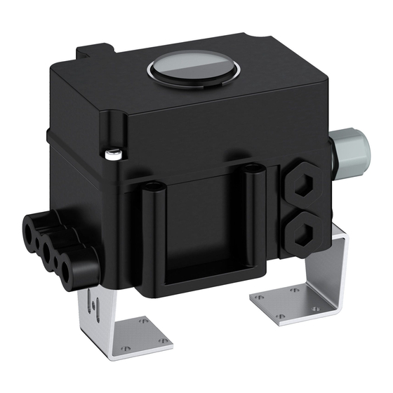
EP100 Analog Positioner
The analog Positioner EP100 with analog input 4 to
20 mA is designed to operate pneumatic valve
actuators. It offers an easy adjustment by means of
switches and potentiometers. The modular
structure of the EP positioner series enables the
feasibility to re-fitt optional equipment (limit switch).
FEATURES
Configuration by means of switches and
potentiometers
Load 300
Low air consumption
Angle range up to 95 degree
Supply air pressure up to 6 bar (90 psig)
Single acting or double acting
Mechanical travel indicator
Reverse polarity protection and interlock diode
Attachment to rotary actuators according to
VDI/VDE 3845
Repair and maintenance operations must be carried out by qualified personnel!
D00002-C-04
Failsafe position in case of failure of
electronics
Protection class IP 65
Additional equipments (compatible to EP200:
Integrated inductive limit switches,
independent of device electronics
Accessories (compatible to EP200:
Gauge attachment for supply air and outputs
Booster relay
Advertisement
Table of Contents

Subscribe to Our Youtube Channel
Related Manuals for EBRO ARMATUREN EP100


Summary of Contents for EBRO ARMATUREN EP100
- Page 1 Master Instruction _____________________________________________________ EP100 Analog Positioner The analog Positioner EP100 with analog input 4 to 20 mA is designed to operate pneumatic valve actuators. It offers an easy adjustment by means of switches and potentiometers. The modular structure of the EP positioner series enables the feasibility to re-fitt optional equipment (limit switch).
-
Page 2: Table Of Contents
EP100 Master Instruction _____________________________________________________ TABLE OF CONTENTS CHAP: CONTENT PAGE CHAP: CONTENT PAGE METHOD OF OPERATION. DECOMMISSIONING General TROUBLE-SHOOTING GUIDE Block diagram Operation Safety Requirements MAINTENANCE 10.1 General LABELS 10.2 Supply filter replacement 10.3 Removal of the electronics unit DESIGN 10.3.1 Conversion of positioner... -
Page 3: Method Of Operation
The positioner can be operated by means of switches and potentiometers. 1.1 General The intelligent positioner EP100 1 and the pneumatic actuator 2 form a control loop with the setpoint value w (from master controller or control system), the output pressure y and the position x of the actuator on valve 3. -
Page 4: Safety Requirements
EP100 Master Instruction _____________________________________________________ 1.4 Safety requirements Accident prevention Explosion protection This device complies with regulations for the prevention (Only if ordered) of accidents Power-Driven Work Aids (VGB 5) of 1st October 1985. Technical data for explosion protection see Product Specifications Sheet PSS EVE0107 A-(en). -
Page 5: Labels
EP100 Master Instruction _____________________________________________________ 2 LABELS A Nameplate B Additional label for option “Limit switches” Nameplate (Example) EP100 Device specification, Model Code ] SER.No [ Serial number ] ECEP [ Number for special engineered version ] D00002-C-04... -
Page 6: Design
EP100 Master Instruction _____________________________________________________ 3 DESIGN 1a Adapter 1/2"-14NPT (see accessories) 11 Connection base for mounting to rotary actuators 1b Cable gland PG 13.5 12 Travel indicator Plug, interchangeable by Pos. 1 17 Air reducing throttle* for output I Screw terminals 11+ 12- for input (w) 18 Air reducing throttle* for output II I–... -
Page 7: Pneumatic Accessories
EP100 Master Instruction _____________________________________________________ 3.1 Pneumatic Accessories When mounting, check the proper seating of the O-rings and bolt on the accessories with the two M8 bolts. Unused outputs are closed by means of plastic plugs. 1/4-18 NPT L x B x H =... -
Page 8: Mounting To Rotary Actuators
Then the direction of rotation may be determined by manual feeding of compressed air. In the powerless EP100 is y1 pressureless and y2 under pressure. Bolt 2 is screwed into actuator drive shaft 1 for subsequent centering of the rotary adaptor 3. -
Page 9: Preparation Of The Actuator
EP100 positioner and actuator are in failsafe position. the EP100 housing. Now place the rotary adaptor 3 with Attach the EP100 on the console in such a way that the two washers 5 on the feedback shaft 9 of the positioner catch of coupling 3 is guided into the groove of shaft 1. -
Page 10: Pneumatic Connections
EP100 Master Instruction _____________________________________________________ 5 PNEUMATIC CONNECTIONS Following alignment and mounting of the positioner to the valve, pneumatic tubing has to be provided. The connection illustrations depend on the respective version. Explanation of abbreviatons: Supply air y1-d Output 1 for direct mounting, depressurized at currentless electronics. -
Page 11: Electrical Connection
-14 AWG). connection 4 is available. Note: When connecting shielded cable connect the cable shield only to the system! Do not connect the cable shield to the EP100! Optional equipment ‘limit switch’ (see terminals 40 ) EP100-x-T, U via inductive sensor... -
Page 12: Start-Up
Switch Position “I”: Switch Position II: Settings via switches and potentiometers For the setting of the EP100 and the adjustment of various parameters 8 dip switches and 5 potentiometers are available. See electronics imprint as follows: Caution! Switches 3 and 8 must be during operation in position “I”. -
Page 13: Setting Of
It has to be If the actuator moves from starting to end position, considered that in a powerless EP100 the output y1 will the direction of rotation of the feedback shaft is to become pressureless and y2 contains air supply pressure. -
Page 14: Setting Of Input Signal Range
EP100 Master Instruction _____________________________________________________ 7.3 Setting of Input Signal Range The following input signal ranges can be set for the EP100 via switches 4 to 7: 100% item 20mA 12mA 12mA 20mA 20mA 20mA 12mA 12mA The switch positions for the setting of various signal ranges are imprinted on the electronics. -
Page 15: Gain (G)
EP100 Master Instruction _____________________________________________________ 7.4 Setting of gain (G) 7.7 Setting of the travel indicator The loop amplification of the positioner is set via The mechanical travel indicator is coupled to the feedback potentiometer P4 for gain (G). The maximum shaft of the positioner by a gear. -
Page 16: Air Reducing Throttles
EP100 Master Instruction _____________________________________________________ 7.8 Air reducing throttles 7.10 Pneumatic test Attention: Service only Attention: Service only Air flow to the actuator may be reduced via air To check the pneumatic parts of the positioner by directly reducing throttles 17 and 18 . - Page 17 EP100 Master Instruction _____________________________________________________ 9 DIAGNOSIS Fault Possible cause Beseitigung Check pneum. connections, Pneum. connections were interchanged see page 10 Check electric connections, Electric connections were interchanged Actuator does not react see page 11 to existing input signal or Wrong setting of zero and span...
- Page 18 10 MAINTENANCE 10.1 General 10.3.1 Conversion of positioner Positioner of the EP series consist of identical The positioner EP100 requires little maintenance. mechanical and pneumatic components and When replacing components during repair work, the accessories. safety requirements on page 4 must be observed! A conversion to either a “digital”...
- Page 19 EP100 Master Instruction _____________________________________________________ 10.4 Replacement of mechanical and pneumatic units First remove the electronics unit 40 (see preceding page). 10.4.3 Replacement of IP module 10.4.1 Amplifier replacement Remove the IP module 48 from base plate and Release the pneumatic amplifier 43 from the base replace with new IP module.
- Page 20 EP100 Master Instruction _____________________________________________________ 11 OPTION 11.1 Limit switch Rebuild to this option resp. exchange Remove three screws 1 including tooth lock washer from plastic cover. Attach limit indicator 2 so that the flattened shaft end 19 contacts the groove of the limit indicator shaft in the positioner.
- Page 21 EP100 Master Instruction _____________________________________________________ 11.1.1 2-wire limit switches Random adjustment of the current values at the end points The limit switch module type “T/U” contains two 2-wire a) Move the actuator to the end position, where you sensors (Type SJ2-N or SJ2-SN) according to the want to adjust the current.
- Page 22 PCLS, CONTROLLER EP100 12.1 Non-intrinsically safe operation 4 - 20 mA The EP100 can be connected directly to the 4 - 20 mA output of the process control system or controller. Load RL is approx. 300 Ohm. EP100 PCS, CONTROLLER...
- Page 23 EP100 Master Instruction _____________________________________________________ DIMENSIONS Subject to alterations - reprinting, copying and translation prohibited. Products and publications are normally quoted here without reference to existing patents, registered utility models or trademarks. The lack of any such reference does not justify the assumption that a product or symbol is free.
Need help?
Do you have a question about the EP100 and is the answer not in the manual?
Questions and answers