Table of Contents
Advertisement
Quick Links
Advertisement
Table of Contents

Subscribe to Our Youtube Channel
Summary of Contents for EBRO ARMATUREN SBU IO-Link
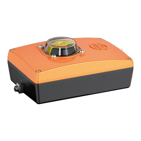
- Page 1 Quick Guide – SBU IO-Link SBU IO-Link Example illustrations, not all possible type variants are shown! Quick Guide in accordance with the EU RED Directive 2014/53/EU in accordance with the EC Machinery Directive 2006/42/EC English language version Revision: 00-05.21...
-
Page 2: Table Of Contents
Quick Guide - SBU IO-Link Table of contents Page GENERAL INFORMATION A01 I NFORMATION ABOUT THESE UICK UIDE A02 E XPLANATION OF SYMBOLS A03 U SE FOR THE INTENDED PURPOSE A04 M SBU IO-L ARKING OF THE MOUNTING AND COMMISSIONING... -
Page 3: A) General Information
These original assembly instructions as well as all other information necessary for safe use must be available to all persons who use the SBU IO-Link at the time of mounting/dismounting and during operation. The SBU IO-Link may neither be mounted nor used without these short operating instructions and the original assembly instructions having been read and understood and being ready to hand at the place of use. -
Page 4: A03 Use For The Intended Purpose
The type plate describes the temperature range, electrical data, EBRO article no. and IP protection class applying to the SBU IO-Link . In addition, the date of manufacture and the CE mark are also printed on it. So that the installed SBU IO-Link remains identifiable, it should not be covered. -
Page 5: B) Mounting And Commissioning
Please contact EBRO ARMATUREN Gebr. Bröer GmbH in case of questions or problems. The SBU IO-Link conforms to the state of the art at the time of delivery and is deemed to be an incomplete machine within the meaning of the Machinery Directive. -
Page 6: B03 Electrical Connection
The associated circuit diagram is affixed inside the inner housing cover. Connect the SBU IO-Link in accordance with the permissible voltage. All electrical connections to the user-side controller are to be checked by an electrician before the initial commissioning. - Page 7 Danger due to incorrect operation. Malfunctions of, or damage to components. The SBU IO-Link may only be connected by an electrician. For external control signals for the solenoid valves, the jumpers J7, J8 and J9 must be removed and the wiring diagram must be observed.
-
Page 8: B04 Commissioning
Quick Guide - SBU IO-Link Commissioning Once the SBU IO-Link has been connected to the controller on the user side in accordance with section B03, no further actions are necessary. The operating states of the SBU IO-Link can be determined and parametrised with the aid of the EBRO Connect App. -
Page 9: D) Storage, Packaging And Transport
Wrap the SBU IO-Link in cardboard, plastic or film packaging. In order to keep the unused SBU IO-Link in a functional condition even over a maximum period of six months, please observe the following storage conditions: ... - Page 10 Quick Guide - SBU IO-Link Page 10 of 10...


Need help?
Do you have a question about the SBU IO-Link and is the answer not in the manual?
Questions and answers