Table of Contents
Advertisement
Quick Links
Advertisement
Table of Contents

Subscribe to Our Youtube Channel
Related Manuals for Lilliput PC-701


Summary of Contents for Lilliput PC-701
- Page 1 Embedded Computer User Manual...
- Page 2 Safety maintenance: Please maintain your system properly to make sure its service life and reduce the damage risk. It should avoid the humidity and extreme temperature when being used. Avoid prolonged exposure of the unit to direct sunlight or strong ultraviolet light. ...
-
Page 3: Table Of Contents
Content 1. Product Description ......................4 1.1. Brief Introduction ....................4 1.2 Optional Functions ....................4 1.3 Basic Parameters ....................4 1.4 3G / 4G Support Parameter & Switch ..............6 2. Structure Function Explanation..................7 3. Extended Cable Definition ....................8 3-1 Serial Port ...................... -
Page 4: Product Description
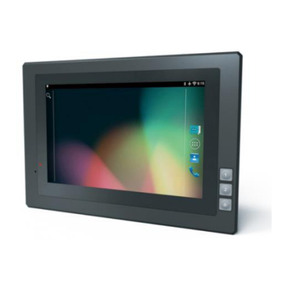
1. Product Description 1.1 Brief Introduction 7"16:10 capacitive touch screen, 1280×800 physical resolution; NXP i.MX 6DualLite 800MHz, 1G RAM, 8G ROM; Android 5.1.1 OS; RS232/GPIO/CAN/LAN/USB2.0/HDMI interfaces; Micro SD (TF) card storage, SIM card slot. 1.2 Optional Functions ... - Page 5 TF card 1.8V/2.95V, up to 64G USB host 2.0×2 USB Device 2.0 (OTG)×1 CAN2.0b×2 Input×4, Output×6 (See section "3. Extended GPIO Cable Definition" for details.) HDMI HDMI 1.4 output 100M×2 Note: If one LAN port for Intranet, the other LAN port for Internet;...
-
Page 6: 4G Support Parameter & Switch
1.4. 3G / 4G Support Parameter & Switch FDD LTE: Band 1 / Band 3 / Band 8 TDD LTE: Band 38 / Band 39 / Band 40 / Band 41 Version 1: China/India/Southe DC-HSPA+ / HSPA+ / HSPA / UMTS: Band1 / ast Asia Band 5 / Band 8 / Band 9 TD-SCDMA: Band 34 / Band 39... -
Page 7: Structure Function Explanation
Structure Function Explanation Power indicator. Reset & burn button. User-definable button 1 (F1). User-definable button 2 (F2). Power on/off button. 1. SIM card slot. 2. USB device. 3. Micro SD (TF) card slot. 4. IOIO 1: (RS232 standard interface, connecting with DB9 standard cable to convert to 3×RS232 ports). -
Page 8: Extended Cable Definition
3. Extended Cable Definition DB9 standard cable DB9 optional cable Item Definition Com 1 RS232 /dev/ttymxc0; Com 2 RS232 /dev/ttymxc1; Com 4 RS232 /dev/ttymxc3; COM 5 RS232 /dev/ttymxc4; RS422 Red A white Z /dev/ttymxc3; Black B Green Y RS485 Red Positive pole /dev/ttymxc4;... - Page 9 CAN/GPIO Item Definition GPIO GPIO57 GPIO 82 GPIO87 GPIO92 Input Yellow Yellow Yellow Yellow GPIO GPIO GPIO 93 GPIO191 GPIO 9 GPIO171 GPIO174 GPIO175 Output Blue Blue Blue Blue Blue Blue GPIO Black CAN1-L CAN1-H CAN2-L CAN2-H Green Green...
-
Page 10: Serial Port
3-1 Serial Port Serial port marking with COM1, COM2, COM4 and COM5 Correspondence between RS232 tail line ports and device nodes COM1=/dev/ttymxc0 COM2=/dev/ttymxc1 COM4=/dev/ttymxc3 COM5=/dev/ttymxc4 3-2 CAN BUS Interface... -
Page 11: Gpio Interface
adb command: Set the bitrate ( baud rate ) before all operations Example: Set the bitrate of the can0 interface to 125kbps: # ip link set can0 up type can bitrate 125000 Quick test Once the driver is installed and the bitrate is set, the CAN interface has to be started like a standard net interface: # ifconfig can0 up and can be stopped like that:... -
Page 12: Memory Card Instruction
2. How to Read or Set Value of Gpio Port Read: Read the value directly from the device node's folder, function is as follows, please refer to the attached demo for detail usage. Public String gpioReadStateOne: (String state) Data read: 0---- ... -
Page 13: Operation Guide
5. Operation Guide 5-1 Basic Operation 5-1-1 Click, Double-click and Slide 5-1-2 Long-press and Drag 5-1-3 Delete... -
Page 14: Icon Bar
Long-press the application icon, and drag it to the recycle bin on the top left corner of screen, then press OK to uninstall this app. 5-2 Icon Bar Icon bar shown on the top left corner of screen, as well as the notice bar; Slide the top bar down to launch the notice bar. -
Page 15: Menu Setting
5-3 Menu Setting 1. Click "Apps" under Settings menu to enter application management. 1-1. Right slide to "ALL": to view and manage all applications. 2. Left slide to “DOWNLOADED”: to view and manage the downloaded applications. - Page 16 2-1. Right slide to “RUNNING”: to view and manage the running applications. Long-press desktop pop-up "Wallpapers", click to enter. 3-1. Choose favorite wallpaper...
- Page 17 4. Click icon to enter Apps list. 4-1. Apps will be displayed in the apps list after installed. Click corresponding icon to enter. 5. Drop down from the top of the screen to enter notification bar. 5-1. The notification bar shows system, running and error notice.
- Page 18 6. Click to launch setting in the apps list. --------------------------------------------------- 6-1. Setting according to users' needs. Click search icon to search function options on the upper right corner of screen. --------------------------------------------------- 6-1-1. To set Wi-Fi, Bluetooth, Ethernet and other functions in “Wireless & networks” category. --------------------------------------------------- 6-1-2.
- Page 19 6-1-4. When unrecovered problems occurred, try to click "Backup & reset" and "Factory data reset", then follow the instructions. Device will delete settings and applications after restart, and restore to factory defaults. (Please backup all important files before reset. Otherwise files will be deleted automatically and restore to factory defaults.) --------------------------------------------------- 7.
-
Page 20: Mounting Methods
6. Mounting Methods VESA 75mm rail slot Embedded mount... -
Page 21: Accessories
7. Accessories Standard accessories: 1. DC 12V adapter 1 piece 2. CAN/GPIO cable 1 piece 3. DB9 cable(RS232x3) 1 piece 4. Mini USB cable 1 piece 5. CD drive 1 piece 6. Fixed screw 4 pieces 7. User Manual 1 copy Optional accessories: 1. -
Page 22: Trouble Shooting
8. Trouble Shootings Power Problem · Cannot boot up 1. Wrong cable connection a) Connect Extended cable with device first, and connect the AC end of DC adapter with DC input port of Extended cable, then the other end of DC adapter connect with power plug socket.
Need help?
Do you have a question about the PC-701 and is the answer not in the manual?
Questions and answers