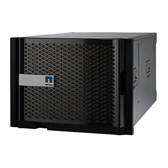
Summary of Contents for NetApp AAF A700
- Page 1 Chassis ONTAP Systems NetApp November 23, 2021 This PDF was generated from https://docs.netapp.com/us-en/ontap-systems/fas9000/chassis-replace- overview.html on November 23, 2021. Always check docs.netapp.com for the latest.
-
Page 2: Table Of Contents
Table of Contents Chassis................. ... -
Page 3: Chassis
Chassis Replace the chassis - AFF A700 and FAS9000 All other components in the system must be functioning properly; if not, you must contact technical support. • You can use this procedure with all versions of ONTAP supported by your system. •... - Page 4 About this task • If you are using NetApp Storage Encryption, you must have reset the MSID using the instructions in the "Returning SEDs to unprotected mode" section of Administration overview with the CLI.
- Page 5 command from the surviving cluster. controller_A_1::> metrocluster heal -phase aggregates [Job 130] Job succeeded: Heal Aggregates is successful. If the healing is vetoed, you have the option of reissuing the command with the metrocluster heal -override-vetoes parameter. If you use this optional parameter, the system overrides any soft vetoes that prevent the healing operation.
-
Page 6: Move And Replace Hardware - Aff A700 And Fas9000
mcc1A::> metrocluster operation show Operation: heal-root-aggregates State: successful Start Time: 7/29/2016 20:54:41 End Time: 7/29/2016 20:54:42 Errors: - 8. On the impaired controller module, disconnect the power supplies. Move and replace hardware - AFF A700 and FAS9000 Step 1: Remove the power supplies Steps Removing the power supplies when replacing a chassis involves turning off, disconnecting, and then removing... - Page 7 Locking button 4. Repeat the preceding steps for any remaining power supplies. Step 2: Remove the fans To remove the fan modules when replacing the chassis, you must perform a specific sequence of tasks. Steps 1. Remove the bezel (if necessary) with two hands, by grasping the openings on each side of the bezel, and then pulling it toward you until the bezel releases from the ball studs on the chassis frame.
- Page 8 Orange release button 3. Set the fan module aside. 4. Repeat the preceding steps for any remaining fan modules. Step 3: Remove the controller module To replace the chassis, you must remove the controller module or modules from the old chassis.
- Page 9 Cam handle release button Cam handle 3. Rotate the cam handle so that it completely disengages the controller module from the chassis, and then slide the controller module out of the chassis. Make sure that you support the bottom of the controller module as you slide it out of the chassis. 4.
- Page 10 NVRAM module when moving it to a new chassis. 1. Unplug any cabling associated with the target I/O module. Make sure that you label the cables so that you know where they came from. 2. Remove the target I/O module from the chassis: a.
- Page 11 Step 5: Remove the De-stage Controller Power Module Steps You must remove the de-stage controller power modules from the old chassis in preparation for installing the replacement chassis. 1. Press the orange locking button on the module handle, and then slide the DCPM module out of the chassis.
- Page 12 guiding the chassis onto the rack rails in a system cabinet or L brackets in an equipment rack. 5. Slide the chassis all the way into the equipment rack or system cabinet. 6. Secure the front of the chassis to the equipment rack or system cabinet, using the screws you removed from the old chassis.
- Page 13 3. Align the bezel with the ball studs, and then gently push the bezel onto the ball studs. Step 10: Install I/O modules Steps To install I/O modules, including the NVRAM/FlashCache modules from the old chassis, follow the specific sequence of steps. You must have the chassis installed so that you can install the I/O modules into the corresponding slots in the new chassis.
-
Page 14: Complete The Restoration And Replacement Process - Aff A700 And Fas9000
Do not completely insert the controller module in the chassis until instructed to do so. 2. Recable the console to the controller module, and then reconnect the management port. 3. Connect the power supplies to different power sources, and then turn them on. 4. - Page 15 ▪ mccip ▪ non-ha b. Confirm that the setting has changed: ha-config show 3. If you have not already done so, recable the rest of your system. 4. Exit Maintenance mode: halt The LOADER prompt appears. Step 2: Running system-level diagnostics After installing a new chassis, you should run interconnect diagnostics.
- Page 16 failures resulting from testing the component. 7. Proceed based on the result of the preceding step. If the system-level diagnostics Then… tests… Were completed without any a. Clear the status logs: sldiag device clearstatus failures b. Verify that the log was cleared: sldiag device status The following default response is displayed: SLDIAG: No log messages are present.
- Page 17 If the system-level diagnostics Then… tests… Resulted in some test failures Determine the cause of the problem. a. Exit Maintenance mode: halt b. Perform a clean shutdown, and then disconnect the power supplies. c. Verify that you have observed all of the considerations identified for running system-level diagnostics, that cables are securely connected, and that hardware components are properly installed in the storage system.
- Page 18 6. Reestablish any SnapMirror or SnapVault configurations. Step 4: Return the failed part to NetApp After you replace the part, you can return the failed part to NetApp, as described in the RMA instructions shipped with the kit. Contact technical support at...
- Page 19 NetApp. The use or purchase of this product does not convey a license under any patent rights, trademark rights, or any other intellectual property rights of NetApp.


Need help?
Do you have a question about the AAF A700 and is the answer not in the manual?
Questions and answers