Advertisement
Quick Links
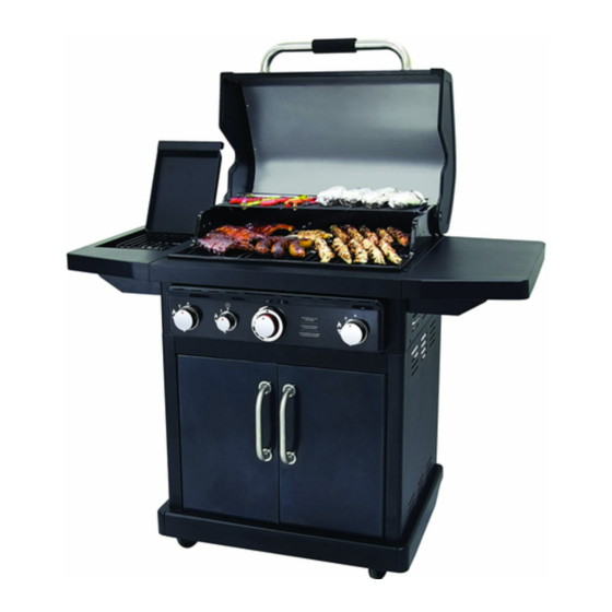
LP Gas Grill
Model #DGP480CSP/DGP480CSP-D
ANS Z21.58a-2008 CSA1.6a-2008
Questions, problems, missing parts? Before returning to your retailer, call our customer
service department at 1-877-447-4768, 8:30 a.m. – 4:30 p.m., CST, Monday – Friday
or e-mail us at customerservice@ghpgroupinc.com.
70-10-003
REV. 003 01-25-11
Advertisement

Subscribe to Our Youtube Channel
Related Manuals for Dyna-Glo DGP480CSP-D


Summary of Contents for Dyna-Glo DGP480CSP-D
- Page 1 LP Gas Grill Model #DGP480CSP/DGP480CSP-D ANS Z21.58a-2008 CSA1.6a-2008 Questions, problems, missing parts? Before returning to your retailer, call our customer service department at 1-877-447-4768, 8:30 a.m. – 4:30 p.m., CST, Monday – Friday or e-mail us at customerservice@ghpgroupinc.com. 70-10-003 REV. 003 01-25-11...
- Page 2 STOP!
- Page 4 22 . Do not modify this grill for use with other indoor or outdoor fixtures, such as countertops or drop-in grill islands. 23 . Do not use this grill indoors.
- Page 5 Fuels used in gas or oil fired appliances and the products of combustion of such fuels, contain chemicals known to the State of California to cause cancer, birth defects or other reproductive harm. This product contains chemicals, including lead and lead compounds, known to the state of California to cause cancer, birth defects or other reproductive harm.
- Page 6 bottom shelf grill body locking caster left shelf assembly caster side burner cooking grate cart left side panel right shelf assembly cart right side panel grease pan cart rear panel grease cup upper front door brace lid handle left door assembly lid handle bezel right door assembly warming rack...
- Page 7 Work Gloves Phillips Screwdriver (optional) Spray Bottle Estimated Assembly Time: 30-45 minutes...
- Page 10 Step 1: Assemble the locking casters (2) and casters (3). Secure the locking casters (2) with four screws each (A), four spring washers each (C) and four flat washers each (B) to the bottom shelf (1), then tighten all the screws. As shown, the flat washer (B) is placed under the spring washer (C).
- Page 11 Step 3: Attach the cart rear panel (6). Insert screws (A) into the cart left side panel (4) and the cart right side panel (5). Do not fully tighten screws (keep approximately 4 to 6mm slack). Align the key holes in the cart rear panel (6) with the two screws just installed into the cart left and right side panels.
- Page 12 Step 5: Attach the cabinet door handles (10) to the doors. Remove the cabinet door handle screws (G) and bezels (11) from cabinet door assemblies. Using 2 of the cabinet door handle sleeves (12), slip each sleeve into the predrilled holes in back of right door assembly (9).
- Page 13 Step 7: Attach the control knobs (13, 14, and 27) and lid handle (21). Attach the control knobs (13, 14, and 27) to the control panel of the body (15). Remove the screws (H) and bezels (22) from the lid handle assembly (21). Align the lid handle bezels (22) and lid handle (21) with the predrilled holes in the top of the lid.
- Page 14 Step 9A: Attach the left side burner assembly (16). Fig. A Insert two screws (F) to the grill body (15) as shown in Fig. A. Do not fully tighten screws (keep approximately 5 mm from surface). Align the key holes in the left side burner assembly (16) with the two screws just installed in the grill body (15).
- Page 15 Step 9B: Attach right shelf assembly (18). Install 2 screws (F) to the grill body (15). Do not fully tighten screws (keep approximately 5 mm from surface). Align the key holes in the right shelf assembly (18) with the 2 screws just installed.
- Page 16 Step 12: Install the grease pan (19) and grease cup (20). Put the grease pan (19) and grease cup (20) in position as illustrated. Step 13: Install 9V battery (26). Place the 9V battery (26) into position in the battery box as shown, then connect the battery box wiring and control knob backlight wiring.
- Page 17 Step 14: Install LP gas cylinder (sold separately). Open the cart doors and insert the LP gas cylinder (sold separately) into the nesting hole located in the bottom shelf. Align the hand screw coupling of the hose/regulator with the threaded valve of the cylinder by turning the LP gas cylinder until positioned correctly.
- Page 18 Fully Assembled Grill Front View Rear View...
- Page 20 To Disconnect: Fully close the tank valve by turning clockwise Turn the coupling nut counterclockwise until the regulator assembly detaches.
- Page 21 Remove all hangings or plastic straps, if present. Before you cook on your new gas grill, it is important to clean your grill with heat. To do this, operate the grill for approximately 15 minutes with the lid closed and all main burner control knobs in the highest position.
- Page 22 LIGHTING THE GRILL WITH A MATCH Warning: Do not lean over grill when lighting. Read instructions before lighting. Main Burners: 1. Insert a match in the end of the match holder that is installed on the inside of the cabinet door. 2.
- Page 23 NOTE: “Burn Off” is NOT necessary for side burner. The porcelain grates have an enamel finish (similar to glass) and should be handled with care not to chip. The electronic ignition requires one “9V” alkaline battery, which is included.
- Page 24 1. Make sure all control knobs Warming Rack are in the OFF position, LP tank valve is closed, and the tank is disconnected from regulator and removed from grill. 2. Open lid and remove warming rack, cooking grates, and heater tents.
- Page 25 6. Disconnect right burner electrode as 7. Slide right main burner out of firebox shown. as shown. 8. Disconnect left burner electrode as 9. Slide left main burner out of firebox as shown. shown.
- Page 26 1. Turn gas off at the control knobs and propane tank. 2. Disconnect LP-Gas cylinder from hose and regulator. 3. Remove warming rack, cooking grates, and heat tents. 4. Detach burner by removing the cotter pins at the back of the burners to detach them from the brackets.
- Page 27 Checking The Flame (main burner only) (main burner only)
- Page 28 Problem Possible Causes Possible Solutions • Fully open tank valve by turning • Tank valve not on or fully opened. No gas flow or an counterclockwise obstructed gas flow. • Check fuel level and replace • Empty tank. fuel if necessary. •...
- Page 29 Problem Possible Causes Possible Solutions • Use match holder found in • Match not reaching burners The burner will not cabinet door. (when holding match with hand). light with a match. • Check fuel level and refill tank if • Empty tank. necessary.
- Page 30 Problem Possible Causes Possible Solutions • Clean the grill components. • Grease and/or residue build-up Excessive flare-ups. on heat tents or in firebox. • Trim the fat from meat and use • Excessive dripping of fat or non-oil based marinades. marinade from food.
- Page 31 For replacement parts, call our customer service department at 1-877-447-4768, 8:30 a.m. – 4:30 p.m., CST, Monday – Friday DYNA-GLO LP GAS GRILL - MODEL #DGP480CSP/DGP480CSP-D Instr. Line # Part # Manual Description Ref. # 103-01001 Grill Body assembly - whole...
- Page 32 DYNA-GLO LP GAS GRILL - MODEL #DGP480CSP/DGP480CSP-D - Continued Instr. Line # Part # Manual Description Ref. # 103-03022 Ignition electrode - Side burner 103-04001 Side Table assembly - Right 103-04002 Side Table - Left - with Side Burner ASSEMBLY complete - INCLUDES side table/side...
- Page 33 Item Name: LP Gas Grill Model #: DGP480CSP/DGP480CSP-D Rated BTU: 57,000 BTU/Hr Product Dimension Assembled: L 52.7” x W 23” x H 46.5” or 1338mm x 585mm x 1180mm Product Weight: 110.23 lb. or 50 kg. This LP Gas Grill is warranted against broken or damaged parts at the time of purchase.
Need help?
Do you have a question about the DGP480CSP-D and is the answer not in the manual?
Questions and answers