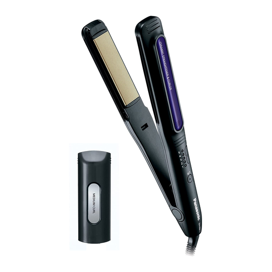
Panasonic EH-HW11 Service Manual
(household) multi-styling straightener
Hide thumbs
Also See for EH-HW11:
- Operating instructions manual (158 pages) ,
- Service manual (16 pages) ,
- Operating instructions manual (44 pages)
Advertisement
Quick Links
TABLE OF CONTENTS
1 Warning -------------------------------------------------------------- 2
2 Specifications ----------------------------------------------------- 2
3 Troubleshooting Guide ----------------------------------------- 3
4 Disassembly and Assembly Instructions ---------------- 5
5 Wiring Connection Diagram ---------------------------------10
6 Schematic Diagram ---------------------------------------------10
7 Exploded View and Replacement Parts List -----------11
(Household) Multi-styling Straightener
Model No.
Model No.
CHINA
PAGE
© Panasonic Corporation 2012 Unauthorized copy-
ing and distribution is a violation of law.
ORDER NO. PEWT1203Z34CE
EH-HW11
EH-HW32
PAGE
Advertisement

Related Manuals for Panasonic EH-HW11


Summary of Contents for Panasonic EH-HW11
-
Page 1: Table Of Contents
3 Troubleshooting Guide ----------------------------------------- 3 4 Disassembly and Assembly Instructions ---------------- 5 5 Wiring Connection Diagram ---------------------------------10 6 Schematic Diagram ---------------------------------------------10 7 Exploded View and Replacement Parts List -----------11 © Panasonic Corporation 2012 Unauthorized copy- ing and distribution is a violation of law. -
Page 2: Warning
• Pb free solder will tend to splash when heated too high (about 1100°F / 600°C). 2 Specifications Model EH-HW11 EH-HW32 Power source/Power consumption AC 100-130V 50-60 Hz 37W(Max.400W) AC 220-240V 50-60 Hz 39W(Max.400W) 130 - 170 °C (5 Level adjustable) -
Page 3: Troubleshooting Guide
3 Troubleshooting Guide (Refer to Wiring Connection Diagram) -
Page 5: Disassembly And Assembly Instructions
4 Disassembly and Assembly Instructions 4.1. Disassembly Instructions 1. Remove Shaft Cover from Main Body by Slotted screw 4. Remove Pivot spring by gripping and pulling it out from driver(Minus Driver). the Main body. 2. Remove Torx screws at Shaft position by Phillips screw driver (Plus Driver). - Page 6 7. Remove Lock Button and Lock Button Spring. 10. Take off Press Plate. 8. Remove Iron Plate of Heater B from Hook. 11. Remove 2 screws of the Housing side by Phillips screw driver (Plus Driver). 9. Remove Slide Plate and Slide Spring. 12.
- Page 7 13. Remove Housing A from Housing B in Grip follow as 14. Take off Iron Plate and Circuit assembly b/k from Hous- below drawing. ing A.
- Page 8 4.2. Assembly and Disassembly Points 1. Shaft Cover fixing point. 2. Housing B Assembly Point.
- Page 9 4.3. Lead wire of Iron Plate(Heater A, Heater B) and Circuit arrangement points. 1. Lead wire of Iron Plate(Heater A assembly b/k) and Circuit assembly b/k arrangement follows as below. 2. Lead wire of Iron Plate(Heater B assembly b/k) arrangement follows as below. 3.
-
Page 10: Wiring Connection Diagram
5 Wiring Connection Diagram 6 Schematic Diagram... -
Page 11: Exploded View And Replacement Parts List
Model No. : EH-HW11 EH-HW32 Model No. : EH-HW11 Exploded View for EH-HW11 - 1 -... - Page 12 Model No. : EH-HW11 EH-HW32 Parts List Ref. Safety Part No. Part Name & Description Q'ty Remarks EHHW11HSAPW HOUSING A ASSEMBLY BLOCK EHHW11FSW FLOATING SPRING 4 *1 EHHW11HAPW HEATER A ASSEMBLY BLOCK EHHW11PKW PACKING (INCLUDE 1 INSULATION TUBE, CONNECTOR CO...
- Page 13 Model No. : EH-HW11 EH-HW32 Model No. : EH-HW32 Exploded View for EH-HW32 - 3 -...
- Page 14 Model No. : EH-HW11 EH-HW32 Parts List Ref. Safety Part No. Part Name & Description Q'ty Remarks EHHW32HSAWW HOUSING A ASSEMBLY BLOCK EHHW32FSW FLOATING SPRING 4 *1 EHHW32HAWW HEATER A ASSEMBLY BLOCK EHHW32PKW PACKING (INCLUDE 1 INSULATION TUBE, CONNECTOR CO...
Need help?
Do you have a question about the EH-HW11 and is the answer not in the manual?
Questions and answers