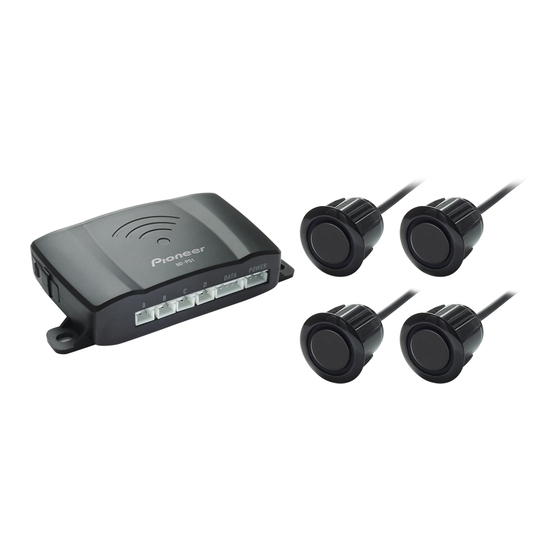
Pioneer ND-PS1 Instructions Manual
Parking sensor
Hide thumbs
Also See for ND-PS1:
- Instruction manual (112 pages) ,
- Installation manual (36 pages) ,
- Manual (14 pages)
Table of Contents
Advertisement
Quick Links
Advertisement
Table of Contents

Related Manuals for Pioneer ND-PS1


Summary of Contents for Pioneer ND-PS1
- Page 1 ND-PS1 Instructions Parking Sensor...
-
Page 2: Important Safeguards
Please read through these instructions so you will know how to operate your product properly. After you have finished reading the instructions, keep this document in a safe place for future reference. This product functions only when connected to a compatible Pioneer receiver (sold separately). For the Customer IMPORTANT SAFEGUARDS • THIS PRODUCT IS A REVERSING AID AND PIONEER ACCEPTS NO RESPONSIBILITY FOR ANY... - Page 3 1.6 m (60 in.) of a detected surface or object. As the vehicle moves, the approximate distance displayed will change in 0.1 m (4 in.) increments. Certain Pioneer receivers may also be compatible with the Pioneer Smart Sync app, which will display an approximate distance and approximate direction from...
- Page 4 LIMITATIONS Fig 1 Fig 2 Fig 1: Object position may be different from the displayed distance due to the sensor position, obstacle, shape, or reflection. If an object is too high If the object is very small When backing up downhill Fig 2: Objects may not be detected properly in the following conditions.
-
Page 5: Can Ices-3 B/Nmb-3 B
CAN ICES-3 B/NMB-3 B This device complies with part 15 of the FCC Rules. Operation is subject to the following two conditions: (1) This device may not cause harmful interference, and (2) this device must accept any interference received, including interference that may cause undesired operation. Information to User Alteration or modifications carried out without appropriate authorization may invalidate the user’s right to operate the equipment. - Page 6 RISK OF ELECTRIC SHOCK, INJURY, OR OTHER HAZARDS. Damage due to improper installation is not covered by the product’s limited warranty. We recommend that only authorized Pioneer service personnel, who have special training and experience in mobile electronics, set up and install this product.
- Page 7 PRECAUTIONS • Installation requires drilling holes into the vehicle bumper, which must be non-metal. • Vehicle must be powered off during product installation. • Make sure engine parts such as the exhaust pipe are not hot before installation. • The sensors must be positioned correctly in order to function properly. • Do not install the control box in or near the vent pipe or wiring.
-
Page 8: After Installation
• Do not shorten any leads. If you do, the protection circuit (fuse holder, fuse resistor or filter, etc.) may fail to work properly. • Use only the parts included with the unit to ensure proper installation. The use of unauthorized parts can cause malfunctions. -
Page 9: General Installation Diagram
GENERAL INSTALLATION DIAGRAM Control box Power cable Sensor Connection cable Pioneer compatible unit Hole saw (sold separately) -
Page 10: Wiring Diagram
WIRING DIAGRAM Reversing light (Red) Ground (Black) To the compatible unit... -
Page 11: Sensor Installation
SENSOR INSTALLATION 1 Fig 1 Fig 1 Fig 1 55 cm 65 cm (1 ft. 9-5/8 in.) (2 ft. 1-5/8 in.) Fig 2 Fig 2 Fig 2 40 cm 40 cm 20 cm 20 cm (1 ft. 3-6/8 in.) (1 ft. 3-6/8 in.) (7-7/8 in.) (7-7/8 in.) Fig 1: The sensor installation height must be between 55 cm (1 ft. - Page 12 SENSOR INSTALLATION 2 19 mm (6/8 in.) Fig 1 Fig 2 WARNING • CHECK THAT THERE IS NO VEHICLE STRUCTURE BEHIND THE HOLE LOCATIONS BEFORE DRILLING. • INSTALLATION OF THE SENSORS REQUIRES A MINIMUM OF 2.54 CM (1 IN.) IN DEPTH (FREE SPACE) BEHIND THE BUMPER SURFACE. • WEAR EYE PROTECTION AND SUITABLE CLOTHING WHEN DRILLING;...
- Page 13 • The control box is not waterproof. It must be installed inside the vehicle. • Find a suitable control box location. Confirm that the sensor wire length is sufficient to reach from the bumper to the control box location before proceeding. • Route the sensor wires into the vehicle to the control box.
-
Page 14: Control Box Installation
CONTROL BOX INSTALLATION... - Page 15 Locate the +12 VDC reverse signal (reverse light or other harness) and connect the red wire from the control box. Connect the black wire from the control box to the chassis ground. Soldering recommended. Use insulation tape to cover the joint. Chassis ground (Black) +12 VDC reverse signal (Red)
-
Page 16: Test After Installation
TEST AFTER INSTALLATION 2.5 m (8 ft. 2-3/8 in.) Test the distance with a hard plate of 100 cm (3 ft. 3-1/8 in.) × 100 cm (3 ft. 3-1/8 in.) or a wall. The farthest detection distance is 2.5m. (8 ft. 2-3/8 in.) (The closest detection distance is 30 cm (11-7/8 in.)). -
Page 17: Specifications
SPECIFICATIONS Control box specifications Nominal voltage : 14.4 V DC Operating voltage : 10.8~15.1 V DC Rated current : 10~30 mA at 14.4 V DC Detection range : 0.3 m (11-7/8 in.)~2.5 m (8 ft. 2-3/8 in.) Operation temperature range : -20 ˚C~ 70 ˚C Dimensions (WxHxD) : 105.3 mm (4-1/8 in.) ×...
Need help?
Do you have a question about the ND-PS1 and is the answer not in the manual?
Questions and answers