
Related Manuals for Saturn South SS9007.3 Mini CT Meter


Summary of Contents for Saturn South SS9007.3 Mini CT Meter
- Page 1 SS9007.3 Mini CT Meter Extended Range Single Phase Meter and Switch User Manual – Version 2 15 Mar 2017...
-
Page 2: Table Of Contents
Table of Contents Safety Notices ..........................3 Quick Reference ..........................4 Product Overview ........................... 5 Technical Specifications ........................6 Commissioning and Installation Instructions .................. 7 Before Installation ........................7 Installation ..........................7 Commissioning ........................13 Switching ............................14 Metering ............................15 Device Clusters and Attributes ...................... -
Page 3: Safety Notices
Servicing of this device in the field is not possible and should not be attempted. If servicing is required, please return this device to Saturn South or an authorised distributor. Opening the product enclosure, for any reason, will render the Product Warranty void. -
Page 4: Quick Reference
Quick Reference SS9007.3 Mini CT Meter Green Amber Connectivity Switch Comment Fast, continuous blinking between Green When device is in the Factory Reset state and Amber. Four blinks of amber, four blinks of green, Connected When device is set to Locate Mode repeating. -
Page 5: Product Overview
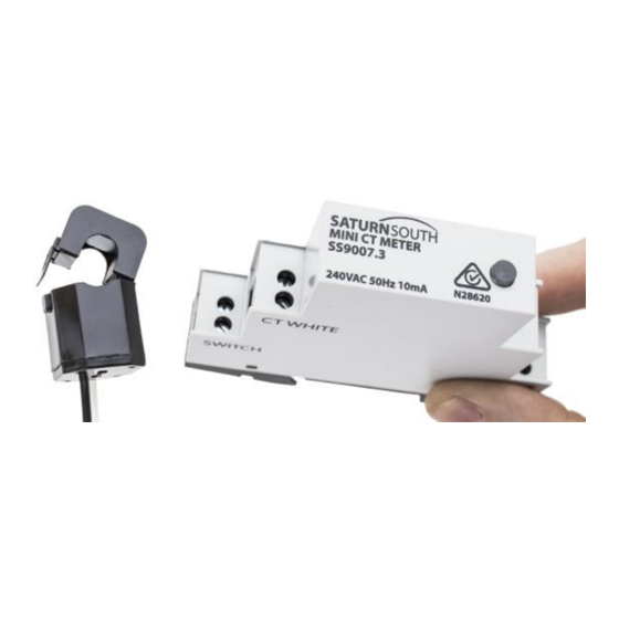
3 Product Overview The SS9007 Mini CT Meter is a compact power metering and load switching device that can be used to monitor and control single phase electrical loads. Designed to sit on a standard switchboard DIN rail, the SS9007 has the same form factor as a standard Miniature Circuit Breaker, and accepts a wide range of external Current Transformers. -
Page 6: Technical Specifications
4 Technical Specifications Type: Single Phase Meter and Switch with External Current Transformer Model: SS9007.3 Operational Voltage Range: 240VAC Operational Frequency Range: 50Hz Operating Temperature Range: -20°C to +65°C Storage Temperature Range: -25°C to +80°C Relative Humidity: 10-95% non-condensing Average Power Consumption: <1.5W Mass: 0.080kg Dimensions: 71 x 90 x 18mm Wire gauge: 0.1mm... -
Page 7: Commissioning And Installation Instructions
The radio environment at the location of installation may be tested to ensure the new device will be able to connect to the existing ZigBee network. For more information on radio environment test equipment and procedures, please contact Saturn South. There are two stages to device installation: 1. - Page 8 Figure 1: Side panel markings for SS9007.3 terminals IMPORTANT: • Ensure the source of the reference phase is isolated before performing these steps. • The SS9007 Mini CT Meter is not rated as a protection device, and must be installed downstream of a readily accessible approved protection device rated to 20A or less in TT and TN power distribution systems.
- Page 9 6. Connect the output of a MCB, RCD, or other protection device to the “Live” (L) terminal of the Mini CT Meter, and a neutral line to the “Neutral” (N) terminal. The protection device used for this purpose need not necessarily be on the same circuit that the device will be monitoring (i.e.
- Page 10 Figure 4: Wiring diagram showing a typical installation of an SS9007 in an IT power distribution system IMPORTANT: • The phase used to power the Mini CT Meter must match the phase being monitored by the CT, or the meter will not produce accurate measurements. 7.
- Page 11 WHITE”), and two SWITCH terminals are marked on the side and end panels of the device enclosure. If the circuit being monitored is connected to a protected neutral (e.g. via an RCD), ensure that the Mini CT Meter is also connected to the same protected neutral, and not to the main neutral link.
- Page 12 IMPORTANT: • If multiple SS9007s are being used to monitor a polyphase phase load, care must be taken to ensure each SS9007 is powered by the corresponding phase. Figure 6: Example three phase installation for a TT or TN power distribution system. Note that each Mini CT Meter is powered by a circuit that is on the same phase as its corresponding CT.
-
Page 13: Commissioning
To complete the installation process, the SS9007 Mini CT Meter must be joined to an existing ZigBee network. The following instructions apply specifically to networks based on the Saturn South ESBox Ethernet-ZigBee Gateway device, however the process will be very similar when using third party ZigBee coordinators. -
Page 14: Switching
6 Switching The two terminals marked 'SWITCH' (‘SW’) on the SS9007.3 Mini CT Meter are connected internally to an isolated DIAC switch with a 100mA current limit. The internal DIAC is typically used to control a third-party external to control loads directly from the switchboard. -
Page 15: Metering
Current is measured using a clip-on current transformer (CT), with nominal primary current ratings of 40A, 120A, and 200A available as standard. Each individual Saturn South meter is calibrated in the final stage of the production process. The calibration procedure matches each device to a particular CT variant, meaning that measurements will not be accurate if a device calibrated for a 120A CT is used with a 40A CT. -
Page 16: Device Clusters And Attributes
8 Device Clusters and Attributes The following Clusters are supported in the Std HA release of the SS9007 Mini CT Meter: • Basic • On/Off • Simple Metering This section lists the available attributes in each supported cluster. A maximum of 11 attributes can be configured for reporting at once. There is only one timer for attribute reports, and attributes will be reported at the interval specified in the most recent report configuration message. -
Page 17: On/Off Cluster
Switch State Simple Metering Cluster Cluster ID: 0x0702 (1794) Manufacturer ID: 0x0000 (0) Saturn South devices expose an expanded set of attributes in a non-standard range within the Simple Metering Cluster on endpoint 10 (0x0A): Attr ID Attr ID Attribute Name... -
Page 18: Troubleshooting
LSSS button sequence on the ESBox to enable ‘Permit Joining’ mode). • Try to join the device again – Saturn South metering devices will initially scan a reduced subset of the full range of available ZigBee channels. If the network is on a channel that is not in the ‘preferred channels’...
Need help?
Do you have a question about the SS9007.3 Mini CT Meter and is the answer not in the manual?
Questions and answers