
Related Manuals for Saturn South SS9005


Summary of Contents for Saturn South SS9005
- Page 1 SS9005 Mini Three Phase Meter User Manual – Version 1.3 – Std HA Release (build V003+) 29 Oct 2015 D501.2-4...
-
Page 2: Table Of Contents
Table of Contents Safety Notices ..........................3 Quick Reference ..........................4 Product Overview ........................... 5 Technical Specifications ........................6 Commissioning and Installation Instructions .................. 7 Before Installation ........................7 Installation ..........................7 Commissioning ........................11 Switching ............................12 Metering ............................13 Device Clusters and Attributes ...................... -
Page 3: Safety Notices
Servicing of this device in the field is not possible and should not be attempted. If servicing is required, please return this device to Saturn South or an authorised distributor. Opening the product enclosure, for any reason, will render the Product Warranty void. -
Page 4: Quick Reference
Quick Reference SS9005 Mini Three Phase Meter – Std HA Release Green Connectivity Switch Comment Fast, continuous blinking between green When device is in the Factory Reset state and red. Four blinks of red, four blinks of green, Connected When device is set to Locate Mode repeating. -
Page 5: Product Overview
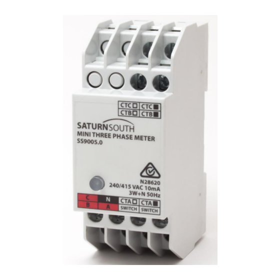
Designed to sit on a standard switchboard DIN rail, the SS9005 has the same form factor as a standard Residual Current Device, and accepts a wide range of external Current Transformers. -
Page 6: Technical Specifications
4 Technical Specifications Type: Three Phase Meter and Switch with External Current Transformers Model: SS9005 Operational Voltage Range: 240/415 VAC Operational Frequency Range: 50Hz Operating Temperature Range: -20°C to +70°C for non-switching variant -20°C to +50°C for switching variant Storage Temperature Range: -25°C to +80°C Relative Humidity: 10-95% non-condensing Average Power Consumption: <2W... -
Page 7: Commissioning And Installation Instructions
2. Ensure that there is adequate mounting space for the device within the switchboard. The SS9005 Mini Three Phase Meter draws power from the phase connected to the ‘A’ terminal, and requires at least 70VAC on terminal ‘A’ relative to Neutral (terminal ‘N’) to operate. A connection to each phase being monitored is required to provide a reference for high accuracy voltage measurements. - Page 8 Ensure the sources of the reference phases are isolated before performing these steps. The SS9005 Mini Three Phase Meter is not rated as a protection device and may only be connected to a circuit that is protected up-stream by an approved circuit breaker.
- Page 9 terminal. The protection devices used for this purpose need not necessarily be on the same circuit that the device will be monitoring (i.e. the circuit to which the CT is connected), although care should be taken to ensure the current sources and voltages share the same phase.
- Page 10 Figure 2: Mini Three Phase Meter monitoring three individual single phase loads 5. If your Mini Three Phase Meter has switching capability, the two terminals marked 'SWITCH' are connected internally to an isolated relay rated for 5A at 240V. The front panel button will glow red to indicate that the relay is closed.
-
Page 11: Commissioning
Commissioning To complete the installation process, the SS9005 Mini Three Phase Meter must be joined to an existing ZigBee network. The following instructions apply specifically to networks based on the Saturn South ESBox Ethernet-ZigBee Gateway device, however the process will be very similar when using third party ZigBee coordinators. -
Page 12: Switching
6 Switching Switching variants of the SS9005 Mini Three Phase Meter can be used to switch loads of arbitrary size indirectly using an inbuilt 5A 240VAC latching relay. If your device is marked with an R on its variant label (e.g. “120A/R”), the two terminals marked 'SWITCH' are connected internally to an isolated relay. -
Page 13: Metering
Region of linearity for 15% to >150% of rated 60A CT (<1% error) primary current Figure 4: Measurement accuracy specification For a full list of measured attributes delivered by the SS9005 Mini Three Phase Meter, please refer to Section 8. -
Page 14: Device Clusters And Attributes
8 Device Clusters and Attributes The following Clusters are supported in the Std HA release of the SS9005 Mini Three Phase Meter: Basic On/Off Simple Metering This section lists the available attributes in each supported cluster. A maximum of 11 attributes can be configured for reporting at once. There is only one timer for attribute reports, and attributes will be reported at the interval specified in the most recent report configuration message. -
Page 15: On/Off Cluster
Safe State Mechanism If the SS9005 is equipped with a switch there is provision for the switch to be automatically returned to a specified safe state in the event that the device loses contact with the Zigbee network, or if the ZigBee coordinator indicates that contact with the ESCo has been lost. - Page 16 Safe state reporting example: The Switch Safe State attribute is set to 3, and the relay is currently OFF (Switch State = 0). The SS9005 loses contact with the ZigBee network, causing the switch state to revert to the selected safe state (ON). The Switch State attribute (attribute 0) will be set to 3, indicating that the switch is on (bit 0 ==1) and a reversion has occurred (bit 1 = 1).
-
Page 17: Simple Metering Cluster
Cluster ID: 0x0702 (1794) Manufacturer ID: 0x0000 (0) Saturn South devices expose an expanded set of attributes in a non-standard range within the Simple Metering Cluster. The following attributes are available on endpoint 1, 2, and 3 (Phase A, Phase B, and Phase C). Any or all of the Phase A, B, and C attributes can be configured for reporting using the ZigBee report configuration/bind process on endpoints 1, 2, and 3 respectively. - Page 18 The frequency value reported in this endpoint is derived from the signal measured on the Phase A voltage input. Only one frequency measurement is made on the SS9005 (it is assumed that all input signals have the same frequency).
-
Page 19: Troubleshooting
LSSS button sequence on the ESBox to enable ‘Permit Joining’ mode). Try to join the device again – Saturn South metering devices will initially scan a reduced subset of the full range of available ZigBee channels. If the network is on a channel that is not in the ‘preferred channels’...
Need help?
Do you have a question about the SS9005 and is the answer not in the manual?
Questions and answers