Table of Contents
Advertisement
Quick Links
Advertisement
Table of Contents

Related Manuals for Schleibinger CDF


Summary of Contents for Schleibinger CDF
- Page 1 Schleibinger CDF/CIF - Freeze-Thaw Testing Equipment User manual Schleibinger Geräte Teubert u. Greim GmbH Gewerbestraße 4 84428 Buchbach Tel. +49 8086 9473110 Fax. +49 8086 9473114 www.schleibinger.com info@schleibinger.com October 11, 2021 Version 3.0...
-
Page 2: Table Of Contents
Contents Contents 1 Introduction 2 Safety Information 2.1 Important Safety Information ....2.2 Protection Switches ..... 2.3 Personal Safety and First Aid . -
Page 3: Contents
10.1 Repair and Maintenance ....10.2 Cleaning of the CDF Machine .... -
Page 4: Introduction
1 Introduction 1 Introduction In this user manual the product „CDF/CIF - Freeze-Thaw Testing Equip- ment“ (hereafter CDF machine) is described. This user manual contain information on the safe, trouble-free and eco- nomical use of the CDF machine. These informations are intended for people who carry out tasks with or in connection with the CDF machine. -
Page 5: Important Safety Information
fire-rated construction. The CDF machine is operating with a refrigerant and requires a careful handling with it. Service and repair jobs at the cooling machine are al- lowed only for well trained and special educated persons. -
Page 6: Safety Instructions For The Refrigerant
2 Safety Information • Avoid splashing when refilling. • Avoid splashing when taking sample container. • In case of contact with eyes, rinse immediately with plenty of water and seek medical advice. • In case of contact with clothes and skin, take off immediately all contaminated clothing and wash the skin immediately with plenty of water for a minimum of 10 minutes. -
Page 7: Intended Use
3 Intended Use 3 Intended Use The CDF machine is designed for the storage of mineral building mate- rials at changing temperatures in a range of - 20 ° C to + 20 ° C and is intended for use in closed rooms. Use the system only for its intended purpose. -
Page 8: Description Of The Appliance
The CDF machine is cooled by means of air cooling. Optionally, the ma- chine can be equipped with a combined air-water cooling „Additional Feature Air and Water Cooling for CDF equipment“. -
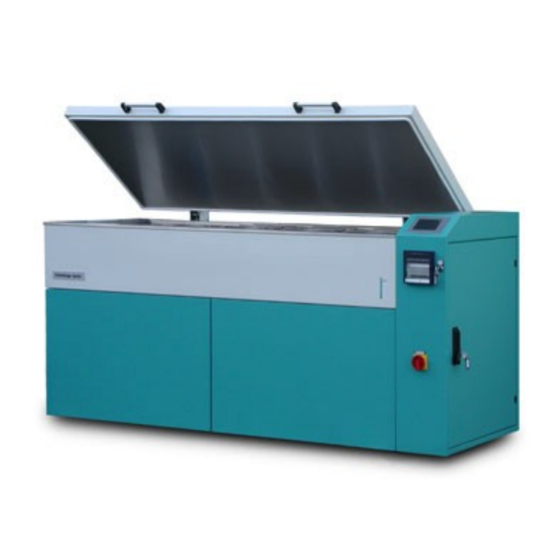
Page 9: Testing Bath With Machine Lid
USB port key switch 10 main switch Figure 1: Structure of the CDF machine. 6.1 Testing Bath with Machine Lid The tub of the testing bath is thermally insulated and is made of high quality stainless steel. For the uniform temperature distribution in the testing bath, the cooling liquid is kept flowing. -
Page 10: Safety Switch
Opening the lid of the cooling bath is only permitted, if the bath tem- perature is close to room temperature. The lid of the CDF machine is equipped with the safety switch (fig. 2). The lock is active, when the temperature is below 0 °... -
Page 11: Notices And Stickers
Notices and stickers are attached on the system. These must be re- newed in the event of loss or illegibility. Mandatory signs can be found on the lid of the CDF machine (fig. 3, 1): Wear protective gloves. Wear safety glasses. -
Page 12: Important Information About The Machine
6 Description of the Appliance 6.12 Important Information about the Machine General dimension (w x d x h) 225 x 95 x 120 cm weight without cooling liquid approx. 560 kg protection IP20 temperature range -20 ° C ... +20 ° C (-40 °... -
Page 13: Delivery And Installation
(fig. 4, (1)) and then the side parts of the wooden box (fig. 4, (2)). • The CDF machine stands on a pallet (fig. 4, (3)). It can be lifted off the pallet with a forklift. Pay attention to the maximum permissible load capacity of the forklift! The empty weight of the CDF machine is approx. -
Page 14: Spatial Requirements
The CDF machine is engineered in accordance with DIN EN 378-1 class A. This means it is allowed to operate the CDF machine in a room where people are sleeping, disabled persons are working, or a lot of not in- structed people are present. -
Page 15: Turn On The Equipment
This information is printed on the type label and can be found on the CDF machine in the area of the power cable. The CDF machine requires a 5-pin Euro power socket and 400 V three- phase power network with a rating of 3x32A CEE32A (3x25A charac- teristic B) and an appropriate circuit protection. -
Page 16: Filling The Equipment
7 Delivery and Installation 7.5 Filling the Equipment Set the CDF machine in level before filling the bath. Check this by a level at the testing bath (7). If necessary, the device can be levelled with four adjustable feet. It should be adjusted to ± 1 mm/m exactly. -
Page 17: Cooling Water Connection For The Combined Air-Water-Cooling (Optional)
The water inlet pressure should be between 1 and 10 bar. The regulation for the cooling of the CDF machine is set via pressure of the condenser. For the pressure of the condenser between 15 and 16 bar air cooling takes place. Higher temperatures due to the environment or inefficient ventilation and heat dissipation cause higher pressure of... -
Page 18: Cube Test And Astm C666 Procedure A (Optional)
CEN/TS 12390-9 usage of the temperature difference of 2 ° C is recommended (fig. 10). The CDF machine equipped with this option is factory set. No changes are required for heating operation. Figure 10: Parameter setting for higher heating power. -
Page 19: Operation Of The Cdf Machine
8 Operation of the CDF Machine This part of the user manual describes all the functions that can be set by the user from the display of the CDF controller. The controller itself is located in the controller unit at the top left. -
Page 20: Start And Stop
(see chapter 8.3). For the CDF test 28 cycles of 12 hours each will be executed. The corresponding number of cycles will expire, if another profile is activated. -
Page 21: Status
8 Operation of the CDF Machine 8.2 Status From the menu item Status the current readings of the CDF machine can be obtained (fig. 13, left). digital inputs: The information about the status of the digital inputs can be shown from Status → Dig. Inputs (fig. 13, right). -
Page 22: Cycle Time
The cycle time is indicated in hours (h) and minutes (min.). With this function, the system can be started at any time during the se- lected temperature profile. For example in case of CDF test, when the system should start at 10 a.m. and the weathering should be determined at 1 to 3 p.m., the cycle time should be set to 7 h and 30 min. -
Page 23: Usb
8 Operation of the CDF Machine 8.4 USB The CDF machine is equipped with an USB port located under the dis- play of the machine. To ensure error-free data transfer, use the supplied USB stick only. Select USB from the main menu (fig. 16). -
Page 24: Setup
8 Operation of the CDF Machine 8.5 Setup The settings for the CDF machine are available from the submenu setup (fig. 17). The set-up parameters are individually adjusted for each testing machine in order to get a proper work of the testing. Any changes can lead to improper work of the controller. -
Page 25: Submenu Items „Profile Select" (Left) And „Profile Input
8 Operation of the CDF Machine • The testing equipment has a refrigeration and temperature control system optimized for the CDF testing. Temperatures lower than -20 ° C should not be used. • The cooling liquid becomes viscous at lower temperatures. De- pending on the glycol to water ratio it may freeze at lower temper- atures. -
Page 26: Graphical Representation Of The Temperature Profile (Left) And Profile Input On The Display Of Cdf Machine (Right)
To complete the testing profile the number of cycles (=number of repeti- tions) has to be entered. The number of cycles depends on the testing procedure for example CDF or CIF procedure with 28 cycles. For con- tinuous working the equipment with the same temperature profile the number of cycles can be set to 32000 maximum. -
Page 27: Profile Assignment For The Buffer (Left) And Display Of The
8 Operation of the CDF Machine difference is no longer active in this case, so that the lead to the nom- inal temperature profile must be taken into account. An example of a possible temperature profile for the buffer is shown as following:... -
Page 28: Display
Figure 23: Sub-menu - Display (left) and "Graph. Display" (right). 8.5.4 Clock The CDF machine differentiates between the cycle time and the real time. The cycle time can be adjusted from the sub-menu Cycle Time (see also chapter 8.3). The real time can be adjusted from the sub-menu Setup →... - Page 29 The switching parameters for the temperature bath are stored in the sub- menu Bath. The designations are based on VDE 2189. The buffer capacity of the CDF machine is approx. 50 litres, which is installed directly under the temperature bath. The temperature of the buffer is based on the target temperature of the bath (temperature pro- file).
-
Page 30: Control Parameters Of The Controller (Left) And Setting Pa
✷✻✵✸ to reset the CDF machine. After entering the code, the display jumps to the previous menu. All the individual parameters of the CDF machine can be found in the controller unit. Make sure, the set parameters are correct! Figure 27: Entering the code for RAM reset. - Page 31 Figure 28: Sub-menu „Misc.“. with activated additional sensor (left) and input of sampling rate (right). • Restart: If this sub-menu is activated, the CDF machine starts au- tomatically after the power failure or after being switched off via the main switch, if the main voltage is applied again and the sys- tem was previously in operation.
-
Page 32: Software Handling From Web Browser
The CDF testing equipment can largely be connected via its built-in net- work interface. The user interface on the PC is the web browser soft- ware. Start and stop of the CDF machine is only possible from the display Please note: on the device!! 9.1 Configuration of the Network access... -
Page 33: Use Of Static Ip Address
Figure 31: Accessing the device with a fixed IP address. 9.1.2 use of static IP address If no network available, the Schleibinger device can be connected di- rectly to a computer or a notebook. For the direct connection use a static IP address. - Page 34 9 Software Handling from Web Browser • Right-click the entry in the chiptool window and select IP configu- ration. • Deactivate ❯s❡ ❉❍❈P . • Enter a static IP address from the same private area as for the computer (fig. 33). The IP addresses of the device and the com- puter must be different e.g.
-
Page 35: Measured Values
9 Software Handling from Web Browser Enter the IP address of the CDF machine in the address field of the web browser. After successful connection, the start screen is displayed (fig. 34). In the upper part of the window the menu bar is located showing different tabs: •... - Page 36 9 Software Handling from Web Browser For graphical display of the measured temperature values select sub- menu «Graphical» (fig. 36). The graphical display can be customized. Please note, the display of the data in the web browser may very depending on the browser. Selection of the channel: The buttons above the graphic allow the selection of the channels to be displayed.
-
Page 37: Data
9 Software Handling from Web Browser 9.3 Data The main menu Data contains the following submenus (fig. 37): • Text • Logfile • Clear Data Figure 37: Main menu - Data. 9.3.1 Display of Temperature Data All recorded measured values are displayed in tabular form after selec- tion Data →... -
Page 38: Logfile And Error Codes
9 Software Handling from Web Browser Figure 39: Measured values in tabular form for import. The measured data is shown in a table. The single tabs are separated by tab characters: ✶✷✼✾✽✽✾✼✵✹ ✹✹✵✸✹✳✺✸✽✷✹✶ ✶✼✳✹✶ ✶✼✳✹✹ ✲✶✷✳✻✶ ✵✳✷✶ ✶✷✼✾✽✽✾✼✻✵ ✹✹✵✸✹✳✺✸✽✽✽✾ ✶✼✳✷✻ ✶✼✳✷✾ ✲✶✷✳✷✻ ✵✳✸✷ ✶✷✼✾✽✽✾✽✶✺... -
Page 39: Profiles
9.4 Profiles The individual temperature profiles can be entered or changed on the CDF machine itself and via web browser. From the menu item Profiles 7 different temperature profiles can be entered (fig. 40. The last profile number 8 is inactive and can be used for practice. -
Page 40: System And Help
• Than the cycle is defined by entering the time in hours and minutes and the corresponding temperature. Please note: • The controller is optimized for the CDF testing and the tem- perature range of -20 ° C to +20 ° C. Every change of the set- tings may worsen the regulation of the controller. -
Page 41: Service Hints
Depending on the type and amount of refrigerant used, an annual in- spection of the CDF machine according to the European F-gas regula- tion EU 517-2014 is required The information on the refrigerant and the amount of refrigerant used can be found in the applicable documents unter „CDF Service Doku-... -
Page 42: Cleaning Of The Cdf Machine
10 Service Hints 10.2 Cleaning of the CDF Machine Use clean water and a soft cloth to clean the surfaces of the machine. Do not use harsh cleaning agents! Stubborn dirt such as cement stone have to be avoided. 10.3 Adjusting the Heat Transfer Fluid A mixture of water and glycol is used as a heat transfer fluid. -
Page 43: Removing The Panels
Figure 43: Removing the panels of the CDF machine. 10.5 Emptying the Heat Transfer Fluid • Remove the panel on the right of the CDF machine (see fig. 43). • Remove the insulation plug under the drain cock under the bath on the right side and near the controller unit (fig. -
Page 44: Battery Change
These parameters will not be saved perma- nently and have to be re-entered after the change of the battery. • Switch off the CDF equipment and pull out the mains plug. • Open the controller unit and remove the acrylic glass cover from the main board of the controller. - Page 45 10 Service Hints problem cause help no circulation in the testing bath Fuse of the pump 1 check the fuse F5.1 visible air in the pump switch the pump off and on sev- eral times (see also chapter ??). «bath too hot» valve Y-K damaged change the coiln Tmax set to low...
-
Page 46: Decommissioning And Disposal
11 Decommissioning and Disposal 11 Decommissioning and Disposal 11.1 Decommissioning The decommissioning of the CDF machine contains the emptying and cleaning of the machine. • Stop the test cycle and set the machine to room temperature. • Open the Lid. - Page 47 List of Figures List of Figures Structure of the CDF machine....Lid lock on the left side of the machine: closed position (left) and open position (right)....
- Page 48 Entering of the temperature profile....Refractometer (left) and antifreeze indicator at -36 ° C (right). 42 Removing the panels of the CDF machine..Drain cock for emptying the cooling liquid under the buffer bath (left) and the filter with the overflow piece in the bath...
Need help?
Do you have a question about the CDF and is the answer not in the manual?
Questions and answers