Table of Contents

Related Manuals for Schleibinger CDF


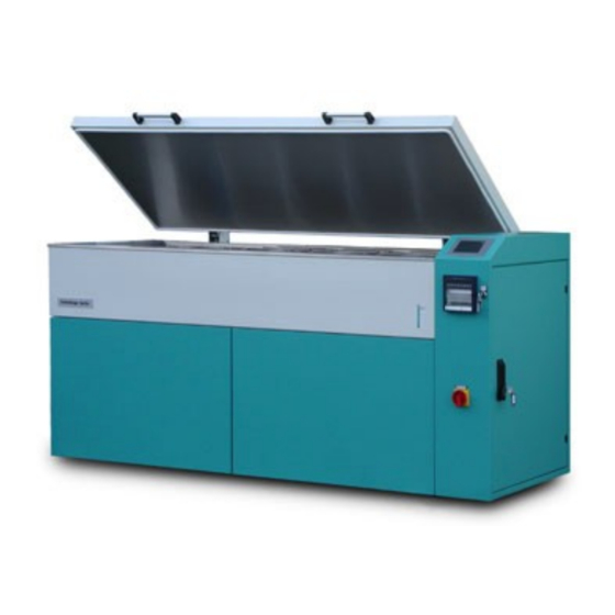
Summary of Contents for Schleibinger CDF
- Page 1 Schleibinger Geräte User Manual CDF-Freeze-Thaw-Testing Machine Schleibinger Geräte Teubert u. Greim GmbH Gewerbestraße 4, 84428 Buchbach Telefon (0 80 86) 9 40 10, Telefax (0 80 869) 9 40 14 Mobil (01 71) 7 32 16 70, (0172) 8 999 196...
-
Page 2: Table Of Contents
OPTION 7 SCHEMATIC DRAWINGS ......38 4 HANDLING THE CONTROLLER....18 7.1 R ........38 EFRIGERANT CHEMATIC 4.1 I ............18 NTRODUCTION 7.2 F ..............39 USES 4.2 K ........18 EYBOARD AND ISPLAY 4.3 H ............18 8 INDEX.............40 ANDLING CDF-Freeze Thaw- Testing Machine page 2... -
Page 3: Introduction
To minimize condense water and energy loss all valves are carefully isolated. All mechanical parts are manufactured on CNC machines, to guaranty that all parts fit in an optimal way. The tin parts are stainless or powder coated according to medicine standards. CDF-Freeze Thaw- Testing Machine page 3... -
Page 4: Installation And Security Hints
Compared with CO (GWP = 1,0) R507 has a high potential for global warming (GWP = 3800). This fact requires a careful handling with the refrigerant. Service and repair jobs at the CDF-Freeze Thaw- Testing Machine page 4... -
Page 5: Internet Connection
The WEB server integrated in the CDF machine displays the the temperature data as well as the actual temperature and some status information. To contact the CDF machine input the IP address of the CDF machine in your web-browser software. For example : http://192.168.1.40... -
Page 6: Chiptool
2.2.1 Chiptool To change this, start the software chiptool.exe delivered with the CDF machine on your PC. This PC must be connected to the same network then the CDF machine. Choose the menu point Chip -Find in the chiptool software. If everything is... -
Page 7: Compactflash Card
2.3 Protection Switches and Personal Safety The machine is equipped with the following safety and security components. This components are adjusted by Schleibinger, Its not allowed to change the settings. (6.2 ): • Over-temperature protection for the heating unit (70 °C) •... - Page 8 Checking the compressor heater Checking the magnetic valves Changing the backup battery of the controller if necessary, latest afer 4 years Repair jobs should be done only by qualified persons Please call Schleibinger for special questions. CDF-Freeze Thaw- Testing Machine page 8...
-
Page 9: Principles Of Operation
Kühlflüssigkeit = coolant liquid; Prüfflüssigkeit = test fluid, water or water with salt; Luft = air; Beton = concrete Also the cube test according to prEN 12390-9 may be run (option) by the CDF machine. In opposite to air cooled test chambers, the cube test cycle may be shortened from 24h to 12h. -
Page 10: Mechanical Construction
Kälte = cool refrigerant; Verdampfer = evaporator; Pumpe = pump; Magnetventile = magnetic valves; Bad = bath; Speicher = buffer, Heizung = heater 3.3 Mechanical construction The CDF machine is a ready to run test chamber. It is based on three main components: • Test-bath • Refrigerating installation... -
Page 11: Testing Tub
In the testing bath the cooling liquid is circulation to ensure a balanced thermal distribution. The gastro norm specimen containers are hanging in the cooling bath. Below the bath the coolant buffer is mounted. 3.3.2 Circulation Unit CDF-Freeze Thaw- Testing Machine page 11... - Page 12 First Time you thin down the glycol coolant with 40 % of water, so that the freeze protection ist -45°C. If you fill all the coolant in the testing-tub the additional liquid comes over into the buffer and the valves. CDF-Freeze Thaw- Testing Machine page 12...
-
Page 13: Freeze Resistance
Check the level again if all specimen containers are mounted. Never run the pumps without liquid. Be sure that no air is sucked by the pumps for a longer time. 3.3.3 Freeze Resistance of the coolant (glycol-tap water mix) CDF-Freeze Thaw- Testing Machine page 13... -
Page 14: Cube Test
-36 °C 3.4 Cube Test Also the cube test according to prEN 12390-9 may be run (option) by the CDF machine. In opposite to air cooled test chambers, the cube test cycle may be shortened from 24h to 12h. This cuts testing time and costs dramatically. - Page 15 Please don´t forget to put the filter over the outlet. Put in most of the specimen containers and fill in additional coolant liquid. Check the liquid level at the level indicator right in front of the instrument. CDF-Freeze Thaw- Testing Machine page 15...
-
Page 16: Key Switch
3.6 Transport of the CDF Machine Empty the coolant from the bath and the buffer, if you like to transport the CDF machine. Lift the machine only at the frame below the bath, never at the coper plates or the electrical cabinet. The cover plates should be fixed additionally, or be transported separately. -
Page 17: Cooling Water Connection
28°C. To reduce the room heating by the machine turn on the volume controller to level 3. If no room heating is allowed, the fan might be switched off by a service man. CDF-Freeze Thaw- Testing Machine page 17... -
Page 18: Handling The Controller
The main switch of the machine should be on at least one hour, before you start a test-run. Therfore the compressor is preheated, the lubricant inside is getting fluid, and the cooling gas is separated from the oil. Otherwise a over pressure error may CDF-Freeze Thaw- Testing Machine page 18... -
Page 19: Status
The cycle time may be set in the appropriate menu. With the CDF test 28 cycles a 24h are run. You may also activate other cycles. If the last cycle is over, the temperature will be kept constant at 20°C. So if you start a new test-run, you have to reset the number of cycles and the cycle time. - Page 20 If a security protection switch is on, it is shown in this menu by an inverse button The actual temperatures are shown in the screen below: CDF-Freeze Thaw- Testing Machine page 20...
-
Page 21: Cycle Time
The cycle time is defined in hours (h) and minutes (min). Hint: You may start the machine at any time. If you like to start the CDF test at 10 am, and the scaling test should be between 1:00 pm and 3:00 pm so adjust the cycle time to 7h 30 min. -
Page 22: Target Value
4.4.1 Target Value Beneath a temperature profile, you may the CDF machine also run at fix temperature. After you put in a temperature here, the machine will run this temperature, until it is stopped again. If the machine is restarted it continues the last active cycle. - Page 23 1. The control algorithm is optimized for the CDF test. Each modification may reduce the controlling quality. As a worst case the controller is no longer stable. 1. The refrigerant installation is also optimized for the CDF cycle. Avoid temperatures below -20°C.
-
Page 24: Display
Five points define 4 profile-segments. The number of cycles depends on the test method (CDF = 28 CIF = 56). If you like to run a cycle at infinity, you may define the number of cycles as 32000 which means 43 years. -
Page 25: Clock
In the clock menu you can set date and time of the real time clock. The controller distinguishes between the cycle time and the real-time clock. The cycle time may be set in the Main-Menu – Cycle Time CDF-Freeze Thaw- Testing Machine page 25... -
Page 26: Manual
Please check this if you are in doubt about your machine setup. 4.5.1 Manual Here you switch on and off each machine unit individually. You see the following menu: Shortcut Unit MK-Mv+Y-1 Compressor and magnetic valve 1 Pump 1 CDF-Freeze Thaw- Testing Machine page 26... -
Page 27: Calibration
4.5.2 DA Calibration This function (DA Output) is for calibrating the line recorder (option). A fix voltage is sent on each channel to the recorder. The following voltages are applied at the 25pin D-Sub connector: CDF-Freeze Thaw- Testing Machine page 27... -
Page 28: Controller
Buffer temperature 4.5.3 Controller Here the configuration of the temperature controller is done. Please contact Schleibinger before you change here anything. 4.5.3.1 Controller Bath The controller for the bath is 4 point switch with hysteresis and Luenberg observer. The following picture shows a quite simplified schematic. - Page 29 You find the real parameters on the calibration sheet inside the electric cabinet. 4.5.3.2 Controller Buffer The CDF machine has a buffer for the coolant of about 50l. Its mounted directly below the bath. The temperature of the buffer is controlled 4..6K below the according bath temperature.
- Page 30 – buffer 1/2“ valve kk1/2 3/8 Cooling depending on temp. Difference -0.005 bath – buffer both valves Self heating by the pumps and the 0.001 enviroment 0.030 Heating unit beobkorr 0.130 Correction factor object - observer CDF-Freeze Thaw- Testing Machine page 30...
-
Page 31: Probes
4.5.4 Probes The CDF machine is using two RTD probes for temperature measurement. One is mounted in the buffer one in the bath. The bath probe is the so called reference probe. It is a high precision RTD 1/10 DIN B with blind slope wiring. In this menu you can set calibration parameters for the sensors. -
Page 32: Ram Reset
Max Temp. Defines the temperature when the machine stops with an Error code. Beneath this function, also an over temperature protection circuit mounted in the heating unit is active. Key Locking locks the touchscreen. This can also be done bey the key-switch at the front panel. CDF-Freeze Thaw- Testing Machine page 32... -
Page 33: Technical Data
Polystyrol foam FCKW-freei Refrigeration Semi-hermetic compressor air cooled (standard) Freezing agent R 507, alternativ R404A Volume 2,99 kg Power Supply Mains 400 V 3PH + N + PE, 50 Hz Power consumption 8,5 kW CDF-Freeze Thaw- Testing Machine page 33... -
Page 34: Service Hints
• Setup the clock 6.2 Values for the Security Devices Refrigerant: High pressure limiter r 26 bar Low pressure limiter -0,3 bar bar Heating: Over temperature limiter r 70 °C Over temperature limiter controler 30°C CDF-Freeze Thaw- Testing Machine page 34... -
Page 35: Elp Yourself
Pump 2 not running change coil, check 24V= Magnetic valve Y-1 not working check the buffer probe buffer temperature to low call the service leak in the refrigerant installation, loss of freezing agent CDF-Freeze Thaw- Testing Machine page 35... - Page 36 Magnetic valve Y-K Change coiln „Bath to hot“ broken check T max in the System T max set to low Menu reference probe in the change probe bath broken to less freezing agent call service CDF-Freeze Thaw- Testing Machine page 36...
- Page 37 PCB board Connection interrupted check the D-Sub-cable from the controler to the display All yellow LEDs on ? If not call the service CDF-Freeze Thaw- Testing Machine page 37...
-
Page 38: Schematic Drawings
7 Schematic Drawings 7.1 Refrigerant Schematic CDF-Freeze Thaw- Testing Machine page 38... -
Page 39: Uses
7.2 Fuses Heater Compressor, fan Pump 1 (main circulation) Pump 2 (buffer circulation) Power supply 24 V= for controller and display magnetic valves Line recorder (option) CDF-Freeze Thaw- Testing Machine page 39... -
Page 40: Index
Restart............................... 32 Schematic Drawings..........................38 Setup................................. 21 Setup of the Machine........................... 4 Start................................18 Status................................ 19 System Menu............................. 26 System Operation............................9 Target Value.............................. 22 Technical Data............................33 Transport............................. 16, 36 Water protection standard........................... 4 CDF-Freeze Thaw- Testing Machine page 40...
Need help?
Do you have a question about the CDF and is the answer not in the manual?
Questions and answers