Table of Contents
Advertisement
Quick Links
Advertisement
Table of Contents

Related Manuals for Smartgen HGM9580

Summary of Contents for Smartgen HGM9580
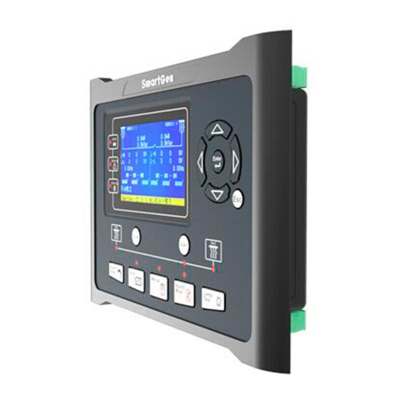
- Page 1 HGM9580 Bus Tie Bus Parallel Unit USER MANUAL Smartgen Technology...
- Page 2 All rights reserved. No part of this publication may be reproduced in any material form (including photocopying or storing in any medium by electronic means or other) without the written permission of the copyright holder. Smartgen Technology reserves the right to change the contents of this document without prior notice. Version history...
- Page 3 HGM9580 BUS TIE BUS PARALLEL UNIT This manual is suitable for HGM9580 bus tie bus parallel unit only. Clarification of notation used within this publication. SIGN INSTRUCTION Highlights an essential element of a procedure to ensure correctness. NOTE Indicates a procedure or practice, which, if not strictly observed, could result in CAUTION! damage or destruction of equipment.
-
Page 4: Table Of Contents
HGM9580 BUS TIE BUS PARALLEL UNIT CONTENTS 1 OVERVIEW ....................... 5 2 PERFORMANCE AND CHARACTERISTICS ........... 6 3 SPECIFICATION ....................7 4 OPERATION ..................... 8 INDICATOR LIGHT ......................8 PUSHBUTTONS ......................9 LCD DISPLAY ....................... 10 4.3.1 MAIN DISPLAY ......................10 4.3.2 USER MENU AND PARAMETERS SETTING MENU .......... -
Page 5: Overview
Chinese, English and other languages interface, and it is reliable and easy to use. HGM9580 Bus Tie Bus Parallel Unit controls a bus breaker which can control the controller to synchronize the two ways buses via MSC CAN if the synchronization requirements have satisfied. -
Page 6: Performance And Characteristics
HGM9580 BUS TIE BUS PARALLEL UNIT 2 PERFORMANCE AND CHARACTERISTICS With ARM-based 32-bit SCM, high integration of hardware and more reliable; 480x272 TFT LCD with backlight, multilingual interface (including English, Chinese or other languages) which can be chosen at the site, making commissioning convenient for factory personnel;... -
Page 7: Specification
HGM9580 BUS TIE BUS PARALLEL UNIT 3 SPECIFICATION Parameter Details Working Voltage DC8. 0V to 35. 0V, continuous power supply <4W (Standby mode: ≤2W) Overall Consumption AC Input: 3 Phase 4 Wire AC15V - AC360V (ph-N) 3 Phase 3 Wire... -
Page 8: Operation
HGM9580 BUS TIE BUS PARALLEL UNIT 4 OPERATION 4.1 INDICATOR LIGHT NOTE: Selected light indicators description: Warning indicator and Alarm indicator: Alarm Type Warning Indicator Alarm Indicator Warning Slow flashing Slow flashing Trip Alarm Fast flashing Running indicator: It is light on when both of bus 1 and bus 2 are normal; off when either of them is abnormal. -
Page 9: Pushbuttons
WARNING: Default password is 00318, user can change it in case of others change the advanced parameters setting. Please clearly remember the password after changing. If you forget it, please contact Smartgen services and send all PD information in the controller page of “ABOUT” to us. -
Page 10: Lcd Display
HGM9580 BUS TIE BUS PARALLEL UNIT 4.3 LCD DISPLAY 4.3.1 MAIN DISPLAY Main screen show pages; use to scroll the pages and to scroll the screen. ★Main Screen, including as below, Bus 1: voltage, frequency, active power, reactive power Bus 2: voltage, frequency, active power, reactive power Some status ★Status, including as below,... - Page 11 HGM9580 BUS TIE BUS PARALLEL UNIT ★ Module settings ★ Synchronization settings Example: > Close Delay Return Form1: Use to scroll settings, > Open Delay Battery setting to enter settings (form 2), to exit Bus setting Breaker setting > settings menu.
- Page 12 HGM9580 BUS TIE BUS PARALLEL UNIT > Close Delay Form 5: Press to change cursor position, 00003 > Open Delay are used for changing cursor value, to confirm setting (form 4), to exit setting (form 4). > Close Delay Form 6: Use to scroll settings.
-
Page 13: Auto Operation
HGM9580 BUS TIE BUS PARALLEL UNIT 4.4 AUTO OPERATION Auto mode is selected by pressing the button; a LED besides the button will illuminate to confirm the operation. 1. When remote start input is active: a) If either of the two buses is deactivate, then bus close signal will be initiated and the bus will be paralleled with the other bus;... -
Page 14: Manual Operation
HGM9580 BUS TIE BUS PARALLEL UNIT 4.5 MANUAL OPERATION Manual mode is selected by pressing the button; a LED besides the button will illuminate to confirm the operation. 1. Press button: If either of the two buses is deactivate, then bus close signal will be initiated and the bus will be paralleled with the other bus. -
Page 15: Protections
HGM9580 BUS TIE BUS PARALLEL UNIT 5 PROTECTIONS 5.1 WARNING ALARMS Warnings are not shutdown alarms and do not affect the operation of the gen-set. Warning alarms does not lead to shutdown. Warning alarms types are as follows: Type Description... -
Page 16: Trip Alarm
HGM9580 BUS TIE BUS PARALLEL UNIT 5.2 TRIP ALARM On initiation of the trip condition the controller will de-energize the ‘Close Generator’ Output without stop the generator. Trip alarm as following, Type Description When the digit input port is set as User Configured and the action Digital Input select “Trip”, it will initiate a trip alarm. -
Page 17: Wiring Connection
HGM9580 BUS TIE BUS PARALLEL UNIT 6 WIRING CONNECTION HGM9580 controller’s rear as following: Description of terminal connection: Cable Functions Remark Size DC input B- 2.5mm Connected with negative of starter battery. Connected with positive of starter battery. If wire DC input B+ 2.5mm... - Page 18 HGM9580 BUS TIE BUS PARALLEL UNIT Cable Functions Remark Size Ground connected Aux. input 4 1.0mm active (B-) Ground connected Aux. input 5 1.0mm active (B-) Ground connected Aux. input 6 1.0mm active (B-) Input COM 17-18 Reserved This is reserved terminals, do not connect to wire.
- Page 19 HGM9580 BUS TIE BUS PARALLEL UNIT Cable Functions Remark Size Bus 1 C-phase voltage Connected to C-phase of Bus 1 (2A fuse is 1.0mm sensing input recommended). Bus 1 N-wire input Connected to N-wire of Bus 1. 1.0mm NOTE: USB ports in controller rear panel are configurable parameter ports, user can directly program controller via PC.
-
Page 20: Scopes And Definitions Of Programmable Parameters
HGM9580 BUS TIE BUS PARALLEL UNIT 7 SCOPES AND DEFINITIONS OF PROGRAMMABLE PARAMETERS 7.1 CONTENTS AND SCOPES OF PARAMETERS Form 1 Items Parameters Defaults Description Battery Setting Standard checking battery Rated Voltage (0-60.0)V 24.0 over/under voltage. Setting value rated voltage’s... - Page 21 HGM9580 BUS TIE BUS PARALLEL UNIT Items Parameters Defaults Description Active Actions (0~2) 0: Warn; 1:Trip 2: Indication Active Delay (0~20.0)s Time from detecting active to confirm LCD display detailed contents when the Description input is active. Flexible Input Port 3...
- Page 22 HGM9580 BUS TIE BUS PARALLEL UNIT Items Parameters Defaults Description Flexible Output Ports Flexible Output Port 1 Contents Setting (0~239) Bus 1 OK. See Form 2 0:Normally open; Active Type (0~1) 1:Normally close Flexible Output Port 2 Contents Setting (0~239) Common Alarm.
- Page 23 HGM9580 BUS TIE BUS PARALLEL UNIT Items Parameters Defaults Description synchronized; If the frequency difference is smaller than 0.1Hz, then the phase will be synchronized; The voltage difference between bus 1 and bus 2. It is considered voltage synchronization when...
-
Page 24: Enable Definition Of Programmable Output Ports
HGM9580 BUS TIE BUS PARALLEL UNIT 7.2 ENABLE DEFINITION OF PROGRAMMABLE OUTPUT PORTS Form 2 Type Description Not Used Reserved Custom Combined 1 Custom Combined 2 Custom Combined 3 Details of function description please see the following. Custom Combined 4... - Page 25 HGM9580 BUS TIE BUS PARALLEL UNIT Auto Mode Action in Auto mode. Bus Load 235~239 Reserved HGM9580 Bus Tie Bus Parallel Unit ISSUE 2014-02-16 Version 1.0 Page 25 of 33...
-
Page 26: Defined Combination Output
HGM9580 BUS TIE BUS PARALLEL UNIT 7.2.1 DEFINED COMBINATION OUTPUT Defined combination output is composed by 3 parts, condition output S1 or S2 and condition output S3. S1 or S2 is TRUE, while S3 is TRUE, Defined combination output is outputting;... -
Page 27: Defined Contents Of Programmable Input Ports
HGM9580 BUS TIE BUS PARALLEL UNIT 7.3 DEFINED CONTENTS OF PROGRAMMABLE INPUT PORTS (ALL ACTIVE WHEN CONNECT TO GRAND (B~)) Form 3 Type Description Including following functions, Indication: indicate only, not warning or shutdown. Warning: warn only. Trip: alarm, generator unloads but not shutdown. - Page 28 HGM9580 BUS TIE BUS PARALLEL UNIT An external button (not self-locking) can be connected Simulate Auto key and pressed as simulate panel. Reserved Simulate Close Button An external button (not self-locking) can be connected Simulate Open Button and pressed as simulate panel.
-
Page 29: Typical Diagram
HGM9580 BUS TIE BUS PARALLEL UNIT 8 TYPICAL DIAGRAM HGM9580 Typical Diagram HGM9580 Bus Tie Bus Parallel Unit ISSUE 2014-02-16 Version 1.0 Page 29 of 33... -
Page 30: Typical Application
HGM9580 BUS TIE BUS PARALLEL UNIT 9 TYPICAL APPLICATION HGM9580 Bus Tie Bus Parallel Unit ISSUE 2014-02-16 Version 1.0 Page 30 of 33... -
Page 31: Installation
Battery Voltage Input NOTE: HGM9580 controller can suit for widely range of battery voltage DC(8~35)V. Negative of battery must be connected with the engine shell. The diameter of wire which from power supply to battery must be over 2.5mm... -
Page 32: Usb
HGM9580 BUS TIE BUS PARALLEL UNIT 11 USB Users can set the controller’s parameters and monitor the controller’s status via the test software which provided by Smartgen company. The connection way between PC and controller as following: HGM9580 Bus Tie Bus Parallel Unit ISSUE 2014-02-16 Version 1.0... -
Page 33: Fault Finding
HGM9580 BUS TIE BUS PARALLEL UNIT 12 FAULT FINDING Symptoms Possible Solutions Check starting batteries; Controller no response with Check controller connection wirings; power. Check DC fuse. Check related switch and its connections according to the Shutdown Alarm in running information on LCD;...
Need help?
Do you have a question about the HGM9580 and is the answer not in the manual?
Questions and answers