
Related Manuals for AOIP CP6632


Summary of Contents for AOIP CP6632
- Page 1 CP6632 Process Calibrator User's Manual RCS: n°447 524 794 00032 – TVA: n°FR13447524794 50-52 Avenue Paul Langevin – F-91130 Ris Orangis – Tel: +33 (0)169 028 900 / Fax: +33 (0)169 020 599 – www.aoip.com...
- Page 2 2 / 35 NTA47209-100A7...
- Page 3 Parts, repairs to the product and service are guaranteed for a period of 90 days. This guarantee only applies to the original purchaser or the end user if he is a client of an AOIP S.A.S approved distributor and does not cover fuses, interchangeable batteries/cells nor any product which, in the opinion of AOIP S.A.S, has been...
- Page 4 4 / 35 NTA47209-100A7...
- Page 5 CONTENT VERIFICATION Content verification The CP6632 has been checked mechanically and electrically prior to dispatch. The necessary precautions have been taken to ensure it reaches the user without being damaged. Nonetheless, it is wise to perform a rapid check to detect any deterioration which may have occurred during transport. If this is the case, inform the carrier immediately thereof.
-
Page 6: Table Of Contents
CP6632 CONTENTS Contents General ..................................7 Introduction ................................7 The instrument ............................... 7 Safety ..................................8 A.3.1 Conformity with safety standards ........................8 A.3.2 Climatic conditions ............................8 A.3.3 Disposal of instrument at end of life ......................... 8 A.3.4 Instructions ..............................8 A.3.5... -
Page 7: General
We are thus able to continue our policy of constant innovation which has served our customers so well for more than 100 years. AOIP S.A.S welcomes any comments or suggestions you might have to enable us to perfect our know-how and make our future products even better. -
Page 8: Safety
CP6632 GENERAL A.3 Safety A.3.1 Conformity with safety standards The instrument complies with the directives in effect concerning both electrical safety (2006/95/CE) and electromagnetic compatibility of electrical measuring equipment (2004/108/CE). This user's manual contains information and warnings that must be adhered to in order to protect the user against the hazards of electric current, ensure safe operation of the appliance, and protect it against incorrect manipulations that could damage it or be detrimental to its safety of use. -
Page 9: Faults And Abnormal Stresses
CAT II 60V: The notion of categories determines the maximum transient voltage that can be applied to the measurement inputs (it is also called overvoltage category). For the CP6632, the maximum permissible overvoltage is 60V (DC or AC) POL 2: The notion of pollution determines the isolation distance between the circuits. -
Page 10: Maintenance
CP6632 GENERAL A.4 Maintenance The instrument must always be reassembled in accordance with the instructions given in this manual. Incomplete or incorrect assembly can jeopardize operator safety. The authority in charge must check regularly that the safety components have not altered over time and perform all the necessary preventive maintenance operations. -
Page 11: Using The Instrument
Power-up B. USING THE INSTRUMENT In order to use the device in all the safety required, all operators must read the paragraph on safety carefully, along with the paragraph below. B.1 Power-up B.1.1 Battery replacement The instrument is supplied with four 1.5V AA batteries. The batteries must be installed in the battery compartment in the back of the instrument. -
Page 12: The Measurement And Simulation Terminals
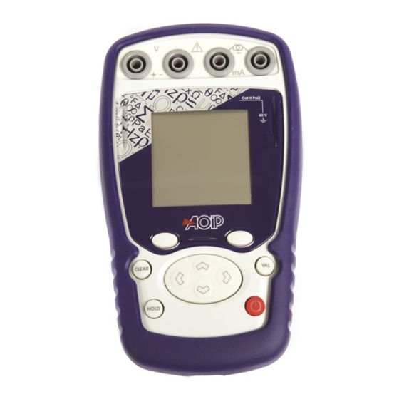
The measurement and simulation terminals The CP6632 is equipped with 4 safety sockets (4 mm diameter). Two of these sockets are for voltage measurement and transmission, while the other two are for current measurement and transmission and the continuity test. -
Page 13: The Usb Connector
USB port (mini B connector) B.1.6 Screen The CP6632 has a backlit graphic liquid crystal display (LCD), with a resolution of 160 x 160 pixels. In normal operating conditions, the display is divided up into seven horizontal fields: The 1 field indicates the operating mode (Measurement or emission). -
Page 14: Starting (After Powering On)
Quadratic scale Filtering %FS (full scale) function Valve test Warning: the CP6632 is in error condition (range exceeded (1)…etc) Incremental mode using the arrows Passive mode (the instrument delivers a +24V source to the sensor) Active mode (the instrument delivers no voltage source) - Page 15 Power-up B.1.8.2 Current measurement Range 0-20 mA (Process) 4-20mA (Process) 25mA Resolution (display) 1 µA (or 10 µA or 100 µA) 1 µA (or 10 µA or 100 µA) 1 µA (or 10 µA or 100 µA) Extent of range -6 mA to +24 mA 3.2 mA to +24 mA -6 mA to +25 mA...
-
Page 16: Programming Modes
CP6632 PROGRAMMING MODES C. PROGRAMMING MODES C.1 Voltage (DC) measurement Measurement or transmission mode is selected using key F2 (mode menu). Using the navigation keys ( and ), move down through the menu to the Measurement field. ... -
Page 17: Current (Dc) Measurement
Voltage / Current measurement Press VAL again to confirm the desired function and call up the measurement screen. Measurement mode provides for display of the Minimum (bottom left), Mean (bottom centre) and Maximum (bottom right) values since the last Min/Max Reset command. ... - Page 18 CP6632 PROGRAMMING MODES Using key F1, go onto the Range field and define the Range. Go into the menu by pressing F2. Select the range using the navigation keys (0/20mA, 4/20mA or 25mA). Press VAL to confirm (the range).
-
Page 19: Current Measurement / Auxiliary Functions
When quadratic scaling is activated, the CP6632 takes the square root of its input and displays the result as a percentage. For example, if the CP6632 is connected to the output of a differential pressure transmitter it displays a result proportional to the flow. -
Page 20: Voltage Or Current (Dc) Transmission
CP6632 PROGRAMMING MODES x (mA) Hart? Using key F1, go onto the Hart field. Using the navigation keys ( and ), select the mode ON or OFF. C.4 Voltage or current (DC) transmission Transmission mode is selected using key F2 (mode menu). - Page 21 Voltage / Current transmission Voltage or current generation / manual editing? Press key F2 to display the edit menu. Using the navigation keys ( and ), select the Manual editing mode and confirm (VAL key). Press VAL again and enter your value using the navigation keys: ...
- Page 22 CP6632 PROGRAMMING MODES Voltage or current generation / single ramp editing? Press key F2 to display the edit menu. Using the navigation keys ( and ), select SINGLE RAMP editing mode and confirm (VAL key). The value displayed is that programmed in the CONFIGURATION/RAMP menu (see next chapter).
-
Page 23: Configuration Of The Ramp Generation
Configuration of the ramp generation C.5 Configuration of the ramp generation The CONFIGURATION/RAMP menu is used for the generation of incremental, single or cyclic ramp signals in both voltage and current. Incremental ramp signal configuration? The figure below illustrates the type of single ramp that can be generated and their parameters: Programming parameters in Incremental mode To : The moment the start of generation key is pressed Td : Delay... - Page 24 CP6632 PROGRAMMING MODES Single ramp signal configuration? The figure below shows the type of single ramp that can be generated along with its parameters: Programming parameters in Single ramp mode To : The moment the start of generation key is pressed...
- Page 25 Configuration of the ramp generation Cyclic ramp signal configuration? The figure below shows the type of cyclic ramp signal that can be generated along with its parameters: Programming parameters in Cyclic ramp mode To: The moment the start of generation key is pressed Td: Delay Tb: Low Level Duration Tm: Rise (rise time)
-
Page 26: Continuity
CP6632 PROGRAMMING MODES C.6 Continuity CONTINUITY mode is a MEASUREMENT mode applied to the current channel (I+, I- terminals). It indicates whether the circuit (the loop) is open or closed. The circuit must be resistive with no active elements. The loop shall be considered closed at loop impedances of 0 to 11 KΩ... -
Page 27: Parameter Settings
Settings D. PARAMETER SETTINGS Contrast adjustment In the CONFIGURATION/SETUP menu, you can adjust the display contrast. Access this menu using the F1 key. Select the Setup field using the navigation keys ( and ), then confirm. Select the Contrast field using the navigation keys ( and ), then confirm. ... -
Page 28: Display Resolution Setting
CP6632 PARAMETER SETTINGS D.3.2 Display resolution setting In the CONFIGURATION/SETUP/PREFERENCE menu, you can select the desired display resolution: Access this menu using the F1 key. Select the Setup field using the navigation keys ( and ), then confirm. ... -
Page 29: Maintenance" Menu
"Maintenance" menu D.4 "Maintenance" menu Not accessible to the user: Consult AOIP who will indicate the procedure to follow for maintenance services. D.5 "About the instrument" menu In the CONFIGURATION/SETUP/ABOUT menu you can find: The reference of the instrument ... -
Page 30: Software Update
About menu. The quickest way to find out if an update is available is to visit the AOIP S.A.S website and look at the “Software” page. To update the firmware, proceed as follows: If necessary, install on the PC the USB driver for communication with AOIP instruments. This driver can be downloaded from our site, along with an information page describing the installation procedure Disconnect the leads connected to the measurement and simulation terminals. -
Page 31: Calibration And Adjustment
Or return the instrument to the address indicated below for verification and calibration. AOIP SAS Rue Dupont Gravé F-14600 Honfleur From France: 01 69 02 89 30 From your country: +33 (0)169 028 950 Fax : +33 (0)169 028 960 Email : sav@aoip.com NTA47209-100A7 31 / 35... -
Page 32: Technical Specifications
CP6632 TECHNICAL SPECIFICATIONS G. TECHNICAL SPECIFICATIONS The indicated levels of precision apply at temperatures of +18°C to +28°C, unless otherwise specified, and are expressed in ± (n % R + C) where R = Reading and C = Constant expressed in practical units and given for a confidence interval of 95%. -
Page 33: Transmission" Function
I < 5 mA G.4 Power supply - Autonomy The CP6632 is designed to function either with four 1.5 V AA batteries or with a 4.8 V battery pack. The following autonomies are given for information. Voltage & current measurement... - Page 34 NTA47209-100A7 18th September, 2015 (English) © 2004, 2015 AOIP S.A.S. All rights reserved. Printed in France. All product names are trademarks of their respective companies. 34 / 35 NTA47209-100A7...
- Page 35 AOIP SAS ZAC DE L'ORME POMPONNE 50-52 Avenue PAUL LANGEVIN F-91130 RIS-ORANGIS From France: 01 69 02 89 88 From your country: +33 (0)169 028 900 Fax: +33 (0)169 028 970 RCS: n°447 524 794 00032 – TVA: n°FR13447524794 50-52 Avenue Paul Langevin – F-91130 Ris Orangis – Tel: +33 (0)169 028 900 / Fax: +33 (0)169 020 599 –...
Need help?
Do you have a question about the CP6632 and is the answer not in the manual?
Questions and answers