
Related Manuals for Balkene Home ASTORIA 63709


Summary of Contents for Balkene Home ASTORIA 63709
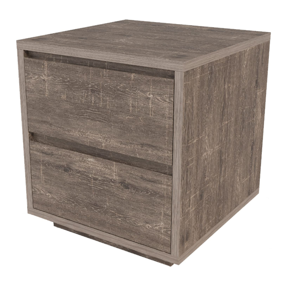
- Page 1 NIGHTSTAND Item#: ATTACH YOUR RECEIPT HERE SAVE THESE INSTRUCTIONS FOR FUTURE REFERENCE. Keep a copy of your proof of purchase or order Purchase Date: Questions, problems, missing parts?
-
Page 2: Before You Begin
INFORMATION BEFORE YOU BEGIN is missing or damaged, do NOT attempt to assemble the product. Please read and understand this entire manual before attempting to assemble, operate or install this product. If you have any questions regarding the product, please all toll-free (866) 985-7877 mail... -
Page 3: Parts List
PARTS LIST CABINET PART DESCRIPTION QUANTITY Drawer Bottom Middle Face Frame Base Front/Back Panel Base Side Panel Upper Face Frame Drawer Cabinet Righ HARDWARE CONTENTS... - Page 4 ASSEMBLY Before beginning assembly, be sure to empty contents of carton and make sure all parts are present. If any parts are missing, please contact Customer Service Place all parts on a soft, level surface for assembly. You will need a -head for assembly.
- Page 5 ASSEMBLY per runner (M3.5x12) 12 toward edge of board. on one side of the Middle Face Frame K. in the diagram above NOTE: the Side Panels in the drawing are shown upside-down. Join the Left and Right Sides by installing the Middle Face Frame as shown.
- Page 6 ASSEMBLY Insert Cam Lock Nuts 2 into the holes on the inside of each Side Panel, rotating the arrows toward the closest panel edge as before. Place the op Panel A upside-down. Align the holes in the edges of the partially-assembled cabinet box with the Cam Bolts previously installed in the Table Top.
- Page 7 ASSEMBLY Bottom Panel B fitt it onto the Dowels previously installed in the bottom edges of the Left and Right Sides. Secure using a Screw 6 near each corner as shown. 6 Screw (M4x40) Assemble the table base by first inserting Cam Lock Nuts 2 into the holes near either end of each Base Side Panel M.
- Page 8 ASSEMBLY Begin assembling the drawers: Attach Drawer Side (Left) G to Drawer Back I using 2 Screws 4, ensuring that the grooved sides are facing in and the groove lines up continuously. Attach the Drawer Side (Right) H in the same manner. Repeat these steps to begin the second drawer.
- Page 9 ASSEMBLY Install the Drawer Runners P/R: Align each Drawer Runner with the wheel toward the back of the drawer and parallel to the Drawer Side. Attach each Runner using 3 Screws 5 positioned as shown in the diagram above the drawer illustration.
- Page 10 an additional year...
Need help?
Do you have a question about the ASTORIA 63709 and is the answer not in the manual?
Questions and answers