Table of Contents
Advertisement
Quick Links
Advertisement
Table of Contents

Summary of Contents for ddtop UTK
- Page 1 DISPLACER LEVEL SWITCH Operation Manual WWW.DDTOP.COM 1 / 11...
- Page 2 If the instructions are not followed, the protection provided by the meter may be destroyed. Trademark, Copyright and Restriction Instructions Dandong Top Electronics Instrument (Group) Co.,Ltd.®, Dandong Top Pump Co., Ltd.®, DDTOP® are registered trademarks of the company. The performance specifications of the meter are effective as of the date of publication and are subject to change without notice.
-
Page 3: Table Of Contents
7.2 Electrical Wiring ............................9 7.3 Debugging Operation Process ......................10 8. Precautions ............................. 10 9 Fault Analysis and Elimination ....................... 11 10 Disassembly ............................11 10.1 Warnings ..............................11 10.2 Waste Removal ............................11 11 Product Certifications ........................... 11 WWW.DDTOP.COM 3 / 11... -
Page 4: Safety Tips
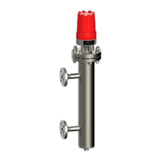
The operations described in this manual are performed by professionally trained and qualified professionals or end-user specialized professionals to complete. 2. Product Manual 2.1 Main Structure of Product igure 1-1 Ball float type Figure 1-1 Displacer type Figure 1-1 Figure 1-1 WWW.DDTOP.COM 4 / 11... -
Page 5: Operating Principle
6.3 MPa. The displacer type is usually used in the working condition that the operating pressure is high or the top mounted alarm setting value is large. Refer to Figure 2 and Figure 3 for the operating principle. WWW.DDTOP.COM 5 / 11... - Page 6 The magnetically controlled switch restores the original state or bias magnetic steel, under the self-weight, back to the new equilibrium position, making the switch contacts switched on or off for the control or alarm of the level. WWW.DDTOP.COM 6 / 11...
-
Page 7: Packaging
3.2.1 Supply Voltage:AC220V DC24V 3.2.2 Output Signal: Relay Contact SPDT or DPDT 4 Dimensional Outline Drawing-Figure 2. If special dimensions are required when ordering, the actual dimensions shall prevail. Figure 3-1 UTK-100A Figure 5 UTK-100B Figure 3-3 UTK-100C WWW.DDTOP.COM 7 / 11... -
Page 8: Unpacking And Inspection
Figure 7 UTK-100D Figure 3-5 UTK-300 Figure 3-6 UTK-400 5 Unpacking and Inspection 5.1 Unpacking Inspection Notice 5.1.1 Check whether the nameplate of the product (Figure 4) is consistent with the information in the supply list. 5.1.2 Check the quantity and material of each part against the packing list. -
Page 9: Installation Technical Requirements
(See Figure 5-2), for DTDP form, the high report is connected to two pairs of normally open points-public end (see Figure 5-3), and the low report is connected to two pairs of normally closed points-public end (see Figure 5-4). WWW.DDTOP.COM 9 / 11... -
Page 10: Debugging Operation Process
8.4 Medium with viscosity higher than 500mPa/s is not suitable for use with the displacer level controller. 8.5 Medium with ferromagnetic particles are not suitable for use with displacer level controller. 8.6 After wiring, tighten the power supply cover to prevent the instrument from getting wet. WWW.DDTOP.COM 10 / 11... -
Page 11: Fault Analysis And Elimination
10.1.2 Refer to the installation procedures in 6.3 and the instructions in section 7.2 Electrical wiring, and dismantle the completed components in reverse order of operation. 10.2 Waste Removal Waste disposal should be carried out in accordance with the current guidelines in each region. 11 Product Certifications WWW.DDTOP.COM 11 / 11...


Need help?
Do you have a question about the UTK and is the answer not in the manual?
Questions and answers