
Subscribe to Our Youtube Channel
Related Manuals for Topcon CV-5000


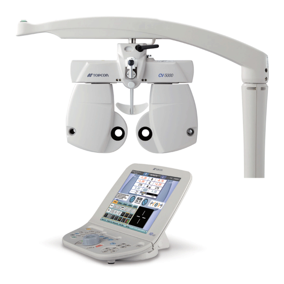
Summary of Contents for Topcon CV-5000
- Page 1 REPAIR MANUAL ISSUED ....APR. 2007 REVISED..... COMPU-VISION CV-5000 TOPCON CORPORATION R-CV5000-0-0704-01...
-
Page 2: Table Of Contents
CONTENTS Page 1. OUTLINE............................ 1 1-1 Features of Product......................1 1-2 Operation Principle....................... 1 1-3 Specifications of Product ...................... 1 1-4 Target Users of This Repair Manual ..................2 1-5 How to Use This Repair Manual ................... 3 1-6 Cautions..........................4 2. -
Page 3: Outline
1. OUTLINE 1-1 Features of Product This instrument is a refractor and the lenses having a variety of power are built in it to measure the refraction of eyes. This instrument is used to measure the correction quantity of refraction and to perform the binocular function test according to the answers of the patient. -
Page 4: Target Users Of This Repair Manual
1-4 Target Users of This Repair Manual Only the service engineer having experience in assembling and adjusting ophthalmic instruments must repair this instrument. For others, it is recommended to take the repair training lessons of TOPCON CORPORATION. − 2 −... -
Page 5: How To Use This Repair Manual
1-5 How to Use This Repair Manual When performing the inspection or when inspecting, adjusting or repairing the instrument for its trouble, follow the flow chart shown below. − 3 − R-CV5000-0-0704-01... -
Page 6: Cautions
1-6 Cautions (1) Before replacing a connector or PCB, turn off the power. (2) When a PCB malfunctions, replace it as a PCB unit. Replaceable PCB Part No. 1. MAIN PCB 43221 51000 2. L PCB 43221 52000 3. R PCB 43221 53000 When you replace the MAIN PCB, remove E²PROM from the old PCB and install it to the new PCB. -
Page 7: Product Outline
2. PRODUCT OUTLINE 2-1 Nomenclature Name Function Examination window The patient’s eyes are observed through this window, and the display lenses are set here. Corneal aligning window The position of the patient’s cornea is seen through this window. Forehead rest knob Adjusts the forehead in the back-and-forth direction. -
Page 8: Optical Arrangement And Names
2-2 Optical Arrangement and Names Patient’s eye Name Function Cover glass at the patient side Prevents eyelashes, dust, etc. from contacting the lens. Spherical lens No. 3 This is a group of high power spherical lenses. Spherical lens No. 2 This is a group 2 of low power spherical lenses. -
Page 9: Electrical Wiring Diagram
2-3 Electrical Wiring Diagram − 7 − R-CV5000-0-0704-01... -
Page 10: Repair
3. REPAIR 3-1 Disassembly and Assembly Procedures 3-1-1 Removal of PD cover Tilt fixing lever Near-point rod holder Screw cover PD cover at patient side Forehead rest knob PD connector cover PD cover at inspector side 1. Remove the screw covers and the two screws CR3 × 6SCr . - Page 11 3-1-2 Removal of lens cover Lens cover at inspector side Lens cover at patient side Face shield 1. Remove the face shield. 2. Remove the two screws CR3 × 3SCr and then remove the lens cover at patient side. * This cover has a claw. Remove it as pushing the arrow section of the lens cover at inspector side.
- Page 12 3-1-3 Removal of lens PCB R PCB L PCB 1. Remove the tape wires and all the connectors from the L PCB. 2. Remove the two screws CR3 × 4Ni and one screw CR2.5 × 4Ni . Then, remove the L PCB.
- Page 13 3-1-4 Removal of MAIN PCB Power box relay cable MAIN PCB 1. Remove the power box relay cable. 2. Remove the tape wires and all the connectors from the MAIN PCB. 3. Remove the five screws CR3 × 4Ni and then remove the MAIN PCB. Note: When installing, attach the insulation sheet.
- Page 14 3-1-5 Removal of spherical unit Spherical unit R Spherical unit L 1. Remove the binding band of the spherical unit. (Zero detection sensor and cornea unit) 2. Remove the wires, which are bound by the harness clip and coating clip. 3.
- Page 15 3-1-6 Removal of lens unit Lens unit L Lens unit R 1. Remove the tape wires at the lens side. 2. Remove the four screws W sems 6S4 × 6S3BZn 3. Remove the four screws W sems 6S4 × 6S3BZn and then remove the lens units L and R.
- Page 16 3-1-7 Removal of CV arm Plate spring Arm cover Disk CV arm Arm mounting shaft 1. Remove the screw CQS2 × 3Cr and then remove the arm cover. 2. Remove the screw 6S6 × 10SCr and then remove the plate spring. 3.
-
Page 17: Names Of Pcb
3-2 Names of PCB 3-2-1 MAIN PCB J100 : The PD sensor is connected. J101 : The convergence sensor is connected. J105 : The power box relay cable is connected. J106 : The convergence motor is connected. J107 : The PD motor is connected. J109 : The near-point chart LED for left eye is connected. - Page 18 3-2-2 L PCB J301 : The spherical motor No. 1 (S1) is connected. J302 : The spherical motor No. 2 (S2) is connected. J303 : The spherical motor No. 3 (S3) is connected. J304 : The cylindrical motor No. 1 (C1) is connected. J305 : The cylindrical motor No.
- Page 19 3-2-3 R PCB J201 : The spherical motor No. 1 (S1) is connected. J202 : The spherical motor No. 2 (S2) is connected. J203 : The spherical motor No. 3 (S3) is connected. J204 : The cylindrical motor No. 1 (C1) is connected. J205 : The cylindrical motor No.
-
Page 20: Specifications Of Switches
3-3 Specifications of Switches 3-3-1 MAIN PCB·SW2 It is necessary to set this DIP SW when correcting the zero detection of each lens. When clearing all the data of EEPROM Set No. 7 and No. 8 to “ON”. (Turn on the power, and the data are cleared.) When clearing part of the EEPROM data (concerned with axis) Set No. - Page 21 3-3-2 How to operate the tool PCB In each tool mode, the following operations can be done without changing the DIP SW: Motor drive test, each window drive (only S1, S2, S3, C1, C2, AX and RPCC) zero detection test, correction of zero detection position and counting the backlash quantity (only RP1, RP2 and CA).
-
Page 22: Names Of Motors And Sensors
3-4 Names of Motors and Sensors 3-4-1 Names of motors in the spherical lens unit and their arrangement [Spherical lens unit for left eye] * Names of motors and their arrangement for right eye are symmetrical to left eye. Spherical motor No. 2 (S2) Spherical motor No. - Page 23 3-4-2 Names of motors in the cylindrical lens unit and their arrangement [Cylindrical lens unit for left eye] * Names of motors and their arrangement for right eye are symmetrical to left eye. RPCC2 zero detection sensor Cylindrical axis zero detection sensor RPCC (RP) motor RPCC1 zero detection sensor Cylindrical motor No.
-
Page 24: Trouble Shooting
(Not in the position of “PD: 64mm”). Resetting is not done correctly and the instrument stops P. 32 in the middle of resetting. Check if the CV-5000 Rattling noise is heard while the PD unit is operating. P. 33 instrument is reset. - Page 25 The instrument is not activated. Is the relay connector of Set the relay connector. the instrument cable set? Fix the MAIN connector to Is the MAIN connector the MAIN PCB. of the instrument set? Is there +24V between +24V and GND in the MAIN PCB? Is the LED of the MAIN PCB turned on?
- Page 26 The continuity of the CV CS cable has already Replace the CV CS cable. been checked. Are the legs of the MAIN PCB and IC short-circuited Prevent short circuit. with metal parts? The +24V voltage Check the PS UNIT. from the PS UNIT has already been checked.
- Page 27 +24V between +24V and GND in POWER PCB has already been checked. +5V between +5V and GND in POWER PCB has already been checked. Replace the MAIN PCB. − 25 − R-CV5000-0-0704-01...
- Page 28 The continuity of Replace the POWER CABLE. POWER CABLE has already been checked. Whether the MAIN PCB is short-circuited with metal parts has Prevent short circuit. already been checked. Replace the MAIN PCB. − 26 − R-CV5000-0-0704-01...
- Page 29 MAIN PCB + L PCB Is there voltage of +24V between +24V and GND in L PCB? Is there voltage of & +5V between +5V and GND in L PCB? Replace the L PCB. MAIN PCB + R PCB Is there voltage of +24V between +24V and GND in R PCB? Is there voltage of...
- Page 30 The +24V pin makes contact Replace the L PCB flexible cable. in L PCB and MAIN PCB. L PCB short-circuits with Prevent short circuit. metal parts. Replace the L PCB. Take the same procedure for R PCB. − 28 − R-CV5000-0-0704-01...
- Page 31 & The +5V pin makes contact Replace the L PCB flexible cable. in L PCB and MAIN PCB. L PCB short-circuits with Prevent short circuit. metal parts. Replace the L PCB. Take the same procedure for R PCB. − 29 − R-CV5000-0-0704-01...
- Page 32 Resetting is not finished. Rattling noise is heavy. Replace the unit (spherical unit). When changing the * The cylindrical unit must be connectors of motors, the motor generating repaired in factory. noise is changed. Replace the PCB. − 30 − R-CV5000-0-0704-01...
- Page 33 & It does not stop and keeps rotating. Replace the unit (spherical unit). The instrument is partly reset * The cylindrical unit must be and then is not activated. repaired in factory. There is voltage of +24V between +24V and GND in MAIN PCB.
- Page 34 Resetting is not done correctly and the instrument stops in the middle of resetting. Replace the unit (spherical unit). The lens does not interfere * The cylindrical unit must be mechanically. repaired in factory. Replace the MAIN PCB. − 32 − R-CV5000-0-0704-01...
- Page 35 Rattling noise is heard while the PD unit is operating. Does the PD unit reach the outside limit position? There is voltage of +5V Replace the PD limit sensor. between TP2 and GND. Replace the MAIN PCB. − 33 − R-CV5000-0-0704-01...
- Page 36 The PD unit interferes Replace the MAIN PCB. mechanically and so it is not activated. Replace the PD unit. − 34 − R-CV5000-0-0704-01...
- Page 37 Convergence is done in the zero detection direction and rattling noise is heard. Does the convergence unit reach the limit position? Replace the convergence limit There is voltage of +5V sensor. between TP1 and GND. Replace the MAIN PCB. − 35 − R-CV5000-0-0704-01...
- Page 38 The PD unit interferes Replace the MAIN PCB. mechanically and so it is not activated. Replace the PD unit. − 36 − R-CV5000-0-0704-01...
- Page 39 Convergence is done in the tilting direction and rattling noise is heard. Does the convergence unit reach the limit position? Replace the MAIN PCB. − 37 − R-CV5000-0-0704-01...
- Page 40 The cornea illumination is not ON when pressing the switch of the operation unit. Is the J216 connector Insert the connector. inserted securely? Is there voltage of Replace the MAIN PCB. 5V or more between pin 1 and pin 2 in J216? Replace the cornea illumination unit.
- Page 41 The cornea illumination is not OFF when pressing the switch of the operation unit. The instrument is operating. The instrument does not operate. Replace the MAIN PCB. − 39 − R-CV5000-0-0704-01...
- Page 42 The near-point chart illumination is not ON when pressing the switch of the operation unit. Is the J109 connector Insert the connector. inserted securely? Is there voltage of Replace the MAIN PCB. 5V or more between pin 1 and pin 2 in J109? Replace the near-point chart illumination.
- Page 43 The near-point chart illumination is not OFF when pressing the switch of the operation unit. The instrument is operating. The instrument does not operate. Replace the MAIN PCB. − 41 − R-CV5000-0-0704-01...
- Page 44 3-5-1 Relation between motors and check pins TP name Silk name Application MAIN PCB PD unit Zero detection sensor CONV Convergence unit Zero detection sensor HEAD IN Unused +24V Power supply: +24V Power supply: GND Power supply: +5V CPU clock L/R PCB Z RP1 Lens cell for RP1...
-
Page 45: Assembly And Adjustment Procedures
3-6 Assembly and Adjustment Procedures 3-6-1 Installation of spherical unit Spherical unit R Spherical unit L Lens zero positioning tool 1. Install the lens zero positioning tool as aligning it with the dowel of the metal plate. 2. Set the spherical units temporarily with the screws CR3 × 5S3BZn3 3. - Page 46 3-6-2 Correction of the spherical unit zero position Zero position correction (SW6/SW10) Zero detection Lens zero positioning tool Reset 1. Install the lens zero positioning tool to the dowel of the metal plate. 2. Set the proper DIP SW of the MAIN PCB to “ON” for the lens to be corrected. (Refer to the attached paper.) 3.
- Page 47 3-6-3 Installation of lens unit Lens unit assembly tool PD gear * Insert only two screws. Turn the PD gear to adjust the right and left hole positions. 1. Install the lens unit assembly tool as aligning it with the dowel of the metal plate. 2.
- Page 48 3-6-4 PD zero position correction Tool PCB mounting section PD correction switch: Clockwise Zero detection PD correction switch: Counterclockwise PD position adjustment tool Reset 1. Set No. 1 of DIP SW to “ON” on the MAIN PCB. 2. Install the tool PCB to the MAIN PCB. 3.
- Page 49 3-6-5 Cornea position adjustment Fixing screw Cornea scale position adjustment tool Cornea vertex position 1. Turn on the power and open the window of each lens. 2. Insert the cornea scale position adjustment tool into the opened window until it stops. 3.
-
Page 50: Version Up Of Software
├ CVPSV###.rom : The ROM software to be newly released for the CV power supply unit (Ver. 1.11 or higher) └ V###.rom : The ROM software to be newly released for CV-5000 (Ver. 1.13 or higher) − 48 − R-CV5000-0-0704-01... - Page 51 • Specify the contents of the CV5000 folder, which is on the desktop, for the driver and continue the installation. 2.4 Click the [USB] icon at the lower right corner on the desktop and make sure that “TOPCON CV-5000” is displayed.
- Page 52 3. How to use “CV-5000 Install Program by USB Ver. 1.10” “CV-5000 Install Program by USB” is used when you perform version up on the personal computer via the USB cable for the ROM softwares of the CV-5000 instrument and the CV power supply unit.
- Page 53 11. Set SW1 and SW2 of DIPSW to “ON”, using tweezers or others. 12. Turn on the power of the compact power supply. 13. Open the CV-5000 folder on the desktop of the personal computer and start “CV5000.exe”. 14. Select “TagerModel: CV-5000”.
- Page 54 Photo of operation Operation procedure 15. Select the ROM file with “OPEN”. Writing 16. Press [START]. If writing starts though the specified ROM file is not the same as the ROM file of the instrument specified in “Target Model”, an error dialog box appears. In this case, check the setting and then open the file again.
-
Page 55: Replacement Of The Pcb For The Near-Point Illumination Led
3-8 Replacement of the PCB for the near-point illumination LED Operation status Operation procedure 1. Remove the near-point rod and near-point chart. 2. Remove the hidden screws and four screws of the cover at the patient side, using the Phillips screwdriver. - Page 56 6. Install the new PCB. Fit the end face of the PCB to the end face of the metal plate and tighten the screws temporarily. Push the PCB in the arrow direction and tighten the screws securely. Set the connector. 7.
-
Page 57: Tools
Usage rank A : Tools necessary to verify during assembly inspection Usage rank B : Tools necessary for repair Tool No. Usage rank Tool Illustration Application CV-5000 Lens zero Used to adjust the lens’ positioning tool zero position CV-5000 Tool PCB... -
Page 58: General Tools
4-2 General Tools • Tester • Screwdriver set • Hexagonal wrench set • Vernier calipers • Radio pliers • Nippers • Soldering iron • Solder • Tweezers • Synchroscope − 56 − R-CV5000-0-0704-01... - Page 59 Printed in Japan 0704-200TH R-CV5000-0-0704-01...
Need help?
Do you have a question about the CV-5000 and is the answer not in the manual?
Questions and answers