Table of Contents
Advertisement
Advertisement
Table of Contents

Related Manuals for Topcon TRC-NW300


Summary of Contents for Topcon TRC-NW300
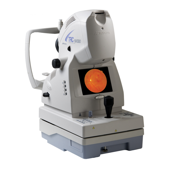
- Page 1 INSTRUCTION MANUAL NON-MYDRIATIC RETINAL CAMERA TRC-NW300...
-
Page 3: Introduction
Before using the instrument, carefully read the "DISPLAY FOR SAFE USE" and the "SAFETY CAUTIONS" to familiarize yourself with the features of the TRC-NW300 NON-MYDRIATIC RET- INAL CAMERA and use it efficiently and safely. -
Page 4: Cautions For Use
To avoid electric shock, turn off the power switch and unplug the power cord and then replace the lamp with a rated one. Disposal When disposing of TRC-NW300 parts, follow the local regulations for disposal and recycling. ENVIRONMENTAL CONDITIONS FOR USE Temperature : 10°C - 40°C... -
Page 5: Environmental Conditions For Packaging In Storage
ENVIRONMENTAL CONDITIONS FOR PACKAGING IN STORAGE Temperature : -20°C - 50°C Humidity : 10% - 95% ENVIRONMENTAL CONDITIONS FOR PACKAGING IN TRANSPORTATION Temperature : -40°C - 70°C Humidity : 10% - 95% CHECKPOINTS FOR MAINTENANCE 1. Periodically inspect the instrument and its parts. 2. -
Page 6: Display For Safe Use
DISPLAY FOR SAFE USE To encourage safe and proper use and to prevent danger to the operator and others or potential damage to properties, important messages are put on the instrument body and inserted in the instruction manual. We suggest that everyone understand the meaning of the following displays, icons and text before reading the "SAFETY CAUTIONS"... -
Page 7: Safety Cautions
SAFETY CAUTIONS WARNINGS Icon Prevention item Page To avoid fire and electric shock in case of leakage, be sure to use a grounded outlet. Do not connect to outlets that are not grounded. To avoid electric shock, do not attempt disassembling, rebuilding and/or repairs on your own. - Page 8 SAFETY CAUTIONS CAUTIONS Icon Prevention item Page To prevent damage and injuries, install the instrument on a level 18, 69 surface. To avoid electric shock, do not handle the plugs with wet fingers. To avoid pain and discomfort to the patient and damage to the patient’s eye, do not brighten the illumination lamp more than nec- essary.
- Page 9 SAFETY CAUTIONS CAUTIONS Icon Prevention item Page Before transporting this instrument, secure the fixing knob on the bottom to prevent movement. This instrument should be carried by two persons. Carrying by one person may cause backache or injury. Holding at areas other than the bottom may also cause injury, as well as falling, thereby damaging the instrument.
-
Page 10: Usage And Maintenance
78. ESCAPE CLAUSES • TOPCON shall not take any responsibility for damage due to fire, earthquakes, actions by third persons and other accidents, or damage due to negligence and misuse by the user and any use under unusual conditions. -
Page 11: Warning Displays And Positions
To ensure safety, this machine provides warning displays. Use the instrument correctly by observing the display instructions. If any of the following dis- play labels are missing, contact your TOPCON dealer at the address listed on the back cover. CAUTION... -
Page 12: Table Of Contents
CONTENTS INTRODUCTION .........................1 CAUTIONS FOR USE ......................2 ENVIRONMENTAL CONDITIONS FOR USE ..............2 STORING PLACE, USAGE PERIOD OR OTHERS ............2 ENVIRONMENTAL CONDITIONS FOR PACKAGING IN STORAGE ........ 3 ENVIRONMENTAL CONDITIONS FOR PACKAGING IN TRANSPORTATION ....3 CHECKPOINTS FOR MAINTENANCE ................3 DISPLAY FOR SAFE USE .................... - Page 13 ELECTRIC RATING ......................67 SYSTEM CLASSIFICATION ....................67 DIMENSIONS AND WEIGHT .................... 68 PURPOSE OF USE ......................68 OPERATION PRINCIPLE ....................68 MAINTENANCE DAILY CHECKUPS ......................69 CLEANING ......................... 78 OPTIONAL ACCESSORIES EXTERNAL FIXATION TARGET EF-2 ................80 OTHER OPTIONAL ACCESSORY ..................80 REFERENCE MATERIAL SHAPE OF PLUG ......................
-
Page 14: Nomenclature
NOMENCLATURE COMPONENT NAMES Access lamlp Connector Main unit Diopter compensation lens selector Focusing knob LED illuminator Color LCD monitor Photography switch Control lever IR filter selector Power lamp Image quality adjustment switch Power supply unit Base brake knob Control panel Fixing knob (for carrying) Chinrest unit Forehead rest... -
Page 15: Control Panel Components
CONTROL PANEL COMPONENTS ID input switch Menu switch Split switch (Zoom playback switch) Thumbnail switch Image playback switch Illumination diaphragm Flash level switch selector switch (-, reset, +) (Upward cursor switch) (Protect switch) Illumination level switch (-, +) Fixation target selector switch (Rightward cursor Chinrest switch... - Page 16 (You can decide the selected item in the menu. Turn ON this switch to print the reviewed image.) Thumbnail switch: P.55 Displays the photographed image in the thumbnail status. * For details, contact your dealer or TOPCON (see the back cover). NOMENCLATURE...
-
Page 17: Components On Color Lcd Monitor Screen
COMPONENTS ON COLOR LCD MONITOR SCREEN Monitor screen Counter Patient ID Right/left eye Alignment bright spot The rest of image quantity in CF CARD AUTO display Diopter compensation lens display Xenon charging display USB memory recognition Flash level compensation display External connection device Small pupil diaphragm recognition display... - Page 18 Preview screen (right after photographing) Counter Patient ID Right/left eye AUTO display Diopter compensation lens display Xenon charging display Flash level compensation Photographic image Small pupil diaphragm Printer recognition display Fixation target position Illumination level Preview screen (in the image playback mode) Date Patient ID 012345678901234567890123-0001...
-
Page 19: Standard Accessories
STANDARD ACCESSORIES Upon unpacking, make sure that all the following standard accessories are included. Numbers in ( ) are the quantities. Power cord (1) Chinrest tissue pin (2) Chinrest tissue paper (1) Fuse (spare) (2) Instruction manual (1) Dust cover (1) Spare parts case (1) Rail cover (2) Screw (4) -
Page 20: Preparations
PREPARATIONS ASSEMBLY PROCEDURE OF THE INSTRUMENT BODY Before transporting this instrument, secure the fixing knob on the bot- CAUTION tom to prevent movement. This instrument should be carried by two persons. Carrying by one person may cause backache or injury. Holding at areas other than the CAUTION bottom may also cause injury, as well as falling, thereby damaging the instrument. - Page 21 Slightly raise the control lever and take out the cushion from the lower part of the base in the arrow direction. Sponge Control lever Styrofoam Sponge Cushion Sliding board (between the instrument body and base unit) Wipe the sliding board with a cloth, etc. to remove dust. Remove the styrofoam from the transportation bracket (A) (the one on the left hand side as viewed from the chinrest side,), slide the base to the left and unscrew the transportation bracket (B).
-
Page 22: Installation/Removal Of Compactflash Card
Insert the CF CARD in the correct direction. As illustrated, place the CF CARD with its memory capacity display on top and push it all the way into the slot. Use the CF CARD specified by TOPCON. For the CF CARD, refer to "OPTIONAL ACCESSORIES" on page 80. -
Page 23: Connecting The Usb Memory
Removal of CF CARD Make sure that the on the instrument is in the "OFF" ( ) position. POWER SWITCH Pull out the CF CARD from the slot. Right after operation of the instrument, the CF CARD may be hot. Be careful when removing it. -
Page 24: Confirmation After Assembly
CONFIRMATION AFTER ASSEMBLY Make sure that the input voltage is within ±10% of the rated voltage for the instrument. If the input voltage exceeds this range, use a constant-voltage power supply (marketed: 400VA or more). Loosen the base brake knob, and move the control lever to verify that it moves smoothly. 1) Right-left movement 2) Back-forth movement 3) Up-down movement... -
Page 25: Connecting The Power Cord
CONNECTING THE POWER CORD To avoid fire and electric shock in case of leakage, be sure to use a WARNING grounded outlet. Do not connect to outlets that are not grounded. CAUTION To avoid electric shock, do not handle the plugs with wet fingers. Make sure that the of the instrument body is OFF ( POWER SWITCH... -
Page 26: Connecting The External Device
Then, connect it. For the use of an image filing system such as IMAGEnet, etc., refer to the instruction manual of each system. For the usable printer, check it by contacting your dealer or TOPCON office (see the back cover). PREPARATIONS... -
Page 27: Menu Setting
MENU SETTING In menu setting, ON/OFF of the auto functions, the flash level and the fixation target can be set. Preparations for menu setting Check the power cord connections. For details about the connection, see "CONNECTING THE POWER CORD" on page 23. Turn the ON (I). - Page 28 Setting of auto focus Set the auto focus function ON/OFF. (When shipped, "ON" is set.) When auto focus is set to ON, focusing is automatically done when taking a picture. On the "MENU" screen, select "AUTO" and press the ENTER SWITCH Press the to select "FOCUS"...
- Page 29 Setting of auto shoot Set the auto shoot function ON/OFF. (When shipped, "ON" is set.) The auto shoot mechanism works as follows: when the fitted alignment bright spot is put into ( ) in the focalized status, the instrument takes a picture automatically without pressing the photography switch.
- Page 30 Setting of auto small pupil Set the auto small pupil function ON/OFF. (When shipped, "ON" is set.) The auto small pupil mechanism works as follows: when the pupil diameter of the patient is too small to take a picture, the instrument automatically changes to the small pupil diaphragm. On the "MENU"...
- Page 31 Setting of auto exposure Set the auto exposure to ON/OFF. (When shipped, "ON" is set.) The auto exposure works to compensate the flash level according to the brightness of fundus. On the "MENU" screen, select "AUTO" and press the ENTER SWITCH Press the to select "EXPO- DOWNWARD CURSOR SWITCH...
- Page 32 Switching of internal/external fixation targets (The external fixation target is an optional accessory.) You can change the internal/external fixation targets. When shipped, "INTERNAL" (internal fixation target) is set. Select "FIXATION" on the "MENU" screen and press the ENTER SWITCH MENU INT / EXT MODE DCF / DCT...
- Page 33 Fixation target pattern You can select the fixation target pattern. When shipped, "P2 (DC)" is set. On the "MENU" screen, select "FIXATION" and press the ENTER SWITCH MENU INT / EXT MODE DCF / DCT FLASH FIXATION MEMORY Press the to select "DCF/DCT"...
- Page 34 Setting of CF CARD Set ON/OFF for storing data into the CF CARD. For installing/removing the CF CARD, refer to page 20. On the "MENU" screen, select "MEMORY" and press the ENTER SWITCH MENU AUTO CF CARD USB MEMORY FLASH FIXATION MEMORY Press the...
- Page 35 Formatting CF CARD Format CF CARD according to the following procedure. On the "MENU" screen, select "MEMORY" and press the ENTER SWITCH Press the to select "CF CARD" UPWARD CURSOR SWITCH DOWNWARD CURSOR SWITCH and then press the ENTER SWITCH Press the to select "FORMAT"...
- Page 36 Removal of the USB memory On the "MENU" screen, select "MEMORY" and press the ENTER SWITCH MENU CF CARD AUTO USB MEMORY FLASH FIXATION MEMORY Press the to select "USB UPWARD CURSOR SWITCH DOWNWARD CURSOR SWITCH MEMORY" and then press the ENTER SWITCH MENU REMOVE...
- Page 37 Menu functions list You can also change the set data for other items in the same way as setting of the auto func- tions. The settable menus are shown below. Setting of the AUTO functions (AUTO) Item Contents Initial setting Explanation FOCUS ON/OFF...
-
Page 38: Reset From Power Save State
When shipped, the power save set time is 10 minutes. To change the set time, contact your dealer or TOPCON (see the back cover). Sometimes the instrument is not set in the power save state due to the focusing condi- tion. -
Page 39: Basic Operations
BASIC OPERATIONS FLOW OF OPERATION Photography procedure explained in "COLOR PHOTOGRAPHY (CENTER)" Turning on the power (P.38) Setting the patient (P.38 - P.39) Setting the illumination level (P.40) Setting the flash level (P.41) Changing the diopter compensation lens (P.42) Small pupil photography (P.50) Centering and photography (P.43 - P.47) When the patient has small pupil Finish procedure (P.48) -
Page 40: Preparation For Photography
PREPARATION FOR PHOTOGRAPHY Applying the power supply Carefully check the power cord connection. For details about the connection, see "CONNECTING THE POWER CORD" on page 23. Turn on any external connection device. Turn ON ( ) the of the instrument. POWER SWITCH Make sure that the title screen and the Monitor screen are displayed. - Page 41 If the chinrest does not move though you press the , it malfunctions. CHINREST SWITCH Set the to the OFF ( ) side and unplug the power cord from the outlet. POWER SWITCH Then, contact your dealer or TOPCON (see the back cover). BASIC OPERATIONS...
-
Page 42: Color Photography (Center)
COLOR PHOTOGRAPHY (CENTER) Setting the illumination level To avoid pain and discomfort to the patient and damage to the CAUTION patient's eye, do not brighten the illumination lamp more than neces- sary. Set the illumination level using the ILLUMINATION LEVEL SWITCH You can verify the current level using the illumination level display on the color LCD monitor. - Page 43 The flash level display can also display the light intensity level (unit: W·s) in addition to the compensation value. For details about the flash level setting, contact your dealer or TOPCON (see the back cover). When the flash level compensation display is changed to the higher level by one step, the flash level is increased by approx.
- Page 44 Changing the diopter compensation lens Pull out the diopter compensation lens selector and change the diopter compensation lens for the patient's eye. On a highly myopic patient, pull out the diopter compensation lens selector by one step and set it to (-) myopia. On a highly hyperopic patient, pull out the diopter compensation lens selector by two steps and set it to (+) hyperopia.
- Page 45 Centering and photography To avoid injury while moving the instrument, do not place your fingers CAUTION into the gap between the instrument body and the power supply unit. To avoid injury to the patient's eyes and nose while moving the instru- CAUTION ment body, keep a safe distance between the patient and the objec- tive lens.
- Page 46 Hold the control lever and pull the instrument backwards toward the operator. As the inter- nal fixation target flickers, instruct the patient to look at the fixation target in the center. Observe the anterior segment image on the color LCD monitor. Move the instrument body using the control lever until you get the patient's eye centered in the color LCD monitor.
- Page 47 Slowly bring the instrument closer to the patient; the retina image will appear on the color LCD monitor. Instruct the patient to look at the green light (internal fixation target). While watching the image on the color LCD monitor, adjust the brightness of the image using the ILLUMINATION LEVEL SWITCH For details about the illumination level setting, see page 40.
- Page 48 When the patient's eye is beyond -13 to +12D, the instruction to insert the diopter compen- sation lens appears on the color LCD monitor screen. At this time, change the diopter compensation lens. Refer to "Changing the diopter compensation lens" on page 42. Since the split lines are off when the diopter compensation lens is anything other than (0), turn the focusing knob so that the fundus image is clearly visible on the color LCD monitor.
- Page 49 When the xenon charging display flickers on the color LCD monitor, photography is not possible even by pressing the PHOTOGRAPHY SWITCH Wait until the xenon charging display turns on before you attempt to take the next image. AUTO F S P Xenon charging display The captured image is stored in the external recording device and displayed on the color LCD monitor.
-
Page 50: Exiting
EXITING Turn OFF( ) the on the instrument body and the external recording POWER SWITCH device. While operating the control lever, move the instrument body so that it comes just above the base. To prevent the base from moving suddenly, turn the base brake knob to the right to lock the base. -
Page 51: Objective Operations
OBJECTIVE OPERATIONS PHOTOGRAPHY OF OTHERS EXCEPT "CENTER" Setting the picture position To set the fixation target position, use the . Each time you FIXATION TARGET SELECTOR SWITCH press the , the setting changes from "D" (center of optic FIXATION TARGET SELECTOR SWITCH disc) to "C"... -
Page 52: Small Pupil Photography
SMALL PUPIL PHOTOGRAPHY When the patient's pupil diameter is small, perform the small pupil photography. When the auto small pupil function is set to "ON", the small pupil diaphragm is automatically set. Take a picture in the same way as the procedure of "COLOR PHOTOGRAPHY (CENTER)" on page 40 and after. - Page 53 For details about the illumination level setting, see "Setting the illumination level" on page 40. Bring the instrument even closer to the patient, and two bright spots for the working dis- tance alignment become visible. Alignment bright spots Split lines When the auto focus function is ON, the instrument changes the split lines into one line.
- Page 54 30° in IMAGEnet, etc. When the image is printed in this setting status, it is printed with the digital magnification 30°. When shipped, the digital magnification mode is not set. For details, contact your dealer or TOPCON (see the back cover). OBJECTIVE OPERATIONS...
-
Page 55: Anterior Segment Photography
ANTERIOR SEGMENT PHOTOGRAPHY Setting the picture position Set the fixation target in the center with the FIXATION TARGET SELECTOR SWITCH Setting the illumination level Set the illumination level by pressing the ILLUMINATION LEVEL SWITCH See "Setting the illumination level" on page 40. Setting the flash level Set the flash level by pressing the FLASH LEVEL SWITCH... - Page 56 Move the instrument body in all directions by the control lever until the patient's eye is in the center of the color LCD monitor. Turn the focusing knob so the anterior segment image is clearly visible on the color LCD monitor, and press the PHOTOGRAPHY SWITCH OBJECTIVE OPERATIONS...
-
Page 57: Image Playback Mode
IMAGE PLAYBACK MODE Reading the image Press the on the Monitor screen. The screen to select the IMAGE PLAYBACK SWITCH recording medium whose image should be read appears on the color LCD monitor. Press the to select "CF CARD" DOWNWARD CURSOR SWITCH UPWARD CURSOR SWITCH or "USB MEMORY". - Page 58 Printing the image When a digital printer applicable to Pict Bridge is connected to the instrument, direct print can be done. Display the image to be printed on the color LCD monitor. Make sure that the printer recognition icon [ ] appears on the color LCD monitor and press the PRINT SWITCH...
- Page 59 Menu in the image playback mode You can execute and stop printing, and delete and protect images according to the following procedure. Press the in the image playback mode, and the following menu is dis- MENU SWITCH played. ID=0000000000000000000000000_0000 '08.06.26 •...
- Page 60 Multi-selection When selecting "SELECT MULTI IMAGES" in the menu while the images are displayed in the thumbnail status, the multi-selection screen appears. On the multi-selection screen, two or more images can be selected at the same time. The background is green on the multi-selec- tion screen.
-
Page 61: Before Requesting Service
BEFORE REQUESTING SERVICE TROUBLESHOOTING Messages displayed during operation Error message Explanation How to cancel NO CFCARD!! The CF card is not inserted. Press the PHOTOGRAPHY SWITCH cancel the error message. Insert the CF CARD or set "OFF" for the CF CARD. CF FULL!! The CF CARD does not have suf- Press the... - Page 62 If one of the following errors has occurred, turn off the power switch and contact your dealer or TOPCON (see the back cover). Error message Explanation COM OPEN ERROR!! The port to be used for internal communication cannot be opened in the instrument.
- Page 63 If, after following the instructions below, you still cannot restore the instrument to a normal con- dition or if the problem does not fall into any of the categories below, contact your dealer or TOPCON (see the back cover). Check List...
- Page 64 Problem Condition Check Page Split lines cannot be • Split line is set to OFF. Turn split line ON (Split switch). seen. • Diopter compensation lens selector is Return diopter compensation lens selector not set to (0). to (0). • Patient's pupil is not large enough. Darken room thoroughly...
-
Page 65: Specifications & Performance
SPECIFICATIONS & PERFORMANCE SPECIFICATIONS Picture angle 45° Working distance 40.7mm φ4.0mm or more (φ3.3mm or more when the small pupil diaphragm Photographable area of pupil is used) Focus range to correct the 0 : -13D to +12D refractive errors of the - : -33D to -12D patient's eye + : +9D to +40D... -
Page 66: Electromagnetic Compatibility
Guidance and manufacturer's declaration - electromagnetic emissions The TRC-NW300 is intended for use in the electromagnetic environment specified below. The customer or the user of the TRC-NW300 should assure that it is used in such an environ- ment. Emissions test... - Page 67 Guidance and manufacturer's declaration - electromagnetic immunity The TRC-NW300 is intended for use in the electromagnetic environment specified below. The customer or the user of the TRC-NW300 should assure that it is used in such an environ- ment. Immunity test...
- Page 68 Guidance and manufacturer's declaration - electromagnetic immunity The TRC-NW300 is intended for use in the electromagnetic environment specified below. The customer or the user of the TRC-NW300 should assure that it is used in such an environ- ment. Immunity test...
-
Page 69: Electric Rating
The TRC-NW300 is intended for use in an electromagnetic environment in which radiated RF disturbances are controlled. The customer or the user of the TRC-NW300 can help prevent elec- tromagnetic interference by maintaining a minimum distance between portable and mobile RF communications equipment (transmitters) and the TRC-NW300 as recommended below, accord- ing to the maximum output power of the communications equipment. -
Page 70: Dimensions And Weight
Degree of protection against harmful ingress of water: IPX0 The TRC-NW300 has no protection against ingress of water. (The degree of protection against harmful ingress of water defined in IEC 60529 is IPX0.) Classification according to the method(s) of sterilization or disinfection recom- mended by the manufacturer: not applicable. -
Page 71: Maintenance
• When not in use, always turn the OFF ( POWER SWITCH Ordering consumables • When ordering consumables and spare parts, contact your dealer or TOPCON (see the back cover) and tell them the article name, article code and quantity. Article name Article code... - Page 72 User maintenance items Item Inspection time Contents Inspection Before using • The instrument must operate correctly. • The objective lens must be free of stains or flaws. Cleaning When the part is stained • Objective lens • External cover, control panel, etc. Replacement As required •...
- Page 73 Replacing the illumination lamp To avoid electric shock, be sure to turn the power switch off and CAUTION unplug the power cord before replacing the lamp. CAUTION To avoid burns, allow lamp to cool before touching. To avoid whitening due to fingerprints, do not touch the lamp with bare NOTE fingers.
- Page 74 Hold the new lamp and slide it into the lamp holder until it stops at the end. Make sure that the lamp is firmly fixed in the lamp holder. Fasten the lamp terminal securely with the two set screws. Attach the lamp house cover by matching the projection at the bottom part of the lamp house cover with the groove of the body cover.
- Page 75 Unscrew the lamp house cover with a coin, etc. to remove it. Loosen the three xenon set screws. Xenon set screw Xenon PCB Hold the xenon PCB at the top and the bottom, slightly slide it to the right and pull it out straight toward the operator’s side.
- Page 76 Changing the fuse To avoid electric shock, unplug the power cord from the grounded out- WARNING let before removing the fuse cover. Do not connect the power cord to the grounded outlet with the fuse cover not correctly attached. To avoid fire in the event of an instrument malfunction, use only fuses WARNING that are fitted to the marked label at the side of the fuse holder.
- Page 77 Supplying the chinrest tissue paper • When the chinrest tissue paper is used up, pull out the chinrest tissue pin and refill the tissue paper. Chinrest tissue pin MAINTENANCE...
- Page 78 Adjusting the color LCD monitor • This instrument is adjusted for the best image quality before shipment, however, readjust- ment may be required due to vibrations, etc., during transportation. • The image quality adjustment switch is on the left side of the color LCD monitor. Contact your dealer for further adjustment of the image quality.
- Page 79 If you want to change other items, repeat Step Select "Save Data" and press the . The set value is saved IMAGE QUALITY MENU SWITCH and the image quality adjustment menu disappears. When the switches are not operated for 10 seconds or more during setting, the setting procedure is finished, the set value is saved and the image quality adjustment menu dis- appears.
-
Page 80: Cleaning
CLEANING Cleaning the external cover, control panel and color LCD monitor screen To prevent the plastic parts of the instrument body from discoloring NOTE and deteriorating, do not use volatile solvents for cleaning, including benzine, thinner, ether, gasoline, etc. When the external cover, control panel and color LCD monitor screen become stained, clean them with a dry cloth. - Page 81 Don't let any strong-alkaline liquid adhere to the objective lens. If such liquid adheres to the lens, immediately wipe it off. If it is difficult to remove a stain from the objective lens, contact your dealer or TOPCON (see the back cover).
-
Page 82: Optional Accessories
This is used to guide the patient's fixed sight. OTHER OPTIONAL ACCESSORY • CompactFlash card (UltraII CompactFlash SDCFH series made by SanDisk Corpora- tion) Use the CompactFlash card specified by TOPCON. If not, TOPCON will not guaran- tee the operation of the instrument. OPTIONAL ACCESSORIES... -
Page 83: Reference Material
REFERENCE MATERIAL SHAPE OF PLUG Country Voltage/frequency Shape of plug Mexico 110V/50Hz Type C&E Argentina 220V/60Hz Type A Peru 220V/60Hz Type A Venezuela 110V/50Hz Type C&E Type A (Most common) Bolivia & Paraguay 220V/60Hz Type H (Infrequently) Chile 220V/60Hz Type A Colombia 110V/50Hz Type C... -
Page 84: Relation Between Setting Of Illumination/ Flash Level And Maximum Radiance
RELATION BETWEEN SETTING OF ILLUMINATION/ FLASH LEVEL AND MAXIMUM RADIANCE When the maximum radiance is "1", the ratio of radiance is shown below in setting of illumination/ flash level. Illumination level Flash level Indicated Indicated Level ratio Level ratio set value set value 0.210 0.022... -
Page 85: Information About The Optical Radiation Hazard To The User
(aphakes) and has not been replaced by a UV-blocking lens or for eyes of very young children. • The value stated for TRC-NW300 gives a measure of hazard potential when the instrument is operated at maximum intensity and maximum aperture. Values of L... - Page 87 • Period of use: Please inform us of the date of purchase. • Instrument’s condition: Please provide us with as much detail as possible on the problem. NON-MYDRIATIC RETINAL CAMERA (TRC-NW300) INSTRUCTION MANUAL 2008 version (2008.12-100TH Date of issue: December 26, 2008 Published by TOPCON CORPORATION 75-1 Hasunuma-cho, Itabashi-ku, Tokyo, 174-8580 Japan.
- Page 88 NON-MYDRIATIC RETINAL CAMERA TRC-NW300 40502 91012 Printed in Japan 0812-100TH...
Need help?
Do you have a question about the TRC-NW300 and is the answer not in the manual?
Questions and answers