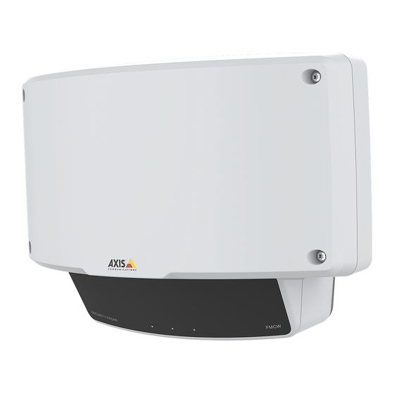
Axis D2110-VE User Manual
Security radar
Hide thumbs
Also See for D2110-VE:
- Installation manual (180 pages) ,
- User manual (61 pages) ,
- User manual (23 pages)
Table of Contents
Advertisement
Quick Links
Advertisement
Table of Contents

Summary of Contents for Axis D2110-VE
- Page 1 AXIS D2110-VE Security Radar User Manual...
-
Page 2: Table Of Contents
AXIS D2110-VE Security Radar Table of Contents Solution overview ......... . . -
Page 3: Solution Overview
AXIS D2110-VE Security Radar Solution overview Solution overview AXIS D2110-VE Fixed dome camera PTZ camera and illuminator Door controller Surveillance center... -
Page 4: Product Overview
AXIS D2110-VE Security Radar Product overview Product overview Control button Network LED Status LED Power LED PoE out LED microSD card slot DC power connector I/O connector Relay connector 10 Grounding screw 11 Network connector (PoE in) 12 Network connector (PoE out) -
Page 5: Mounting Height
The detector is designed to be mounted 3.5 m above ground. When the detector is mounted higher up the near detection limit is impaired. To improve the near detection limit, tilt the detector downwards with AXIS T91R61 Wall Mount. The table shows the detection range for a human entering in the middle of the detection zone. -
Page 6: Find The Device On The Network
Find the device on the network Find the device on the network To find Axis devices on the network and assign them IP addresses in Windows®, use AXIS IP Utility or AXIS Device Manager. Both applications are free and can be downloaded from axis.com/support. -
Page 7: Additional Settings
AXIS D2110-VE Security Radar Additional settings Additional settings Need more help? You can access the built-in help from the device’s webpage. The help provides more detailed information on the device’s features and their settings. Configure the detector The detector is ready to use as soon as it is installed. The default live view will show the radar coverage and any detected movement, and you can add detection zones and rules right away. -
Page 8: How To Configure The Detector
AXIS D2110-VE Security Radar Additional settings Image requirements: • Supported file formats are jpeg and png. • Use an image with the same proportions (16:9) or resolution (1920x1080) as the live view. If the image is smaller it will be scaled to fit the window. -
Page 9: Set Up Rules And Alerts
AXIS D2110-VE Security Radar Additional settings 1. Go to Settings > Radar > General and select Coexistence. Set up rules and alerts How to record video from a camera when motion is detected This example explains how to set up the detector and a camera so that the camera starts recording to the SD card five seconds before the detector detects motion and to stop one minute after. -
Page 10: How To Turn On A Light When Motion Is Detected
It is possible to use the information about objects’ positions from the detector to make a PTZ camera track objects. To do this, install the application AXIS Radar Autotracking for PTZ on your VMS server (or another computer with access to both the camera and the detector), and follow the instructions in the application. -
Page 11: About Detection Zones
AXIS D2110-VE Security Radar Additional settings About detection zones To determine where to detect motion, you can add multiple zones. Different zones can be used to trigger different actions. There are two types of zones: • An include zone is an area in which moving objects will trigger rules. The default include zone matches the entire area covered by the detector. - Page 12 AXIS D2110-VE Security Radar Additional settings Enable Short-lived object and set a delay time from when the radar starts tracking an object until it can trigger and alarm. The timer starts when the radar first detects the object, not when the object enters the include zone.
-
Page 13: Troubleshooting
AXIS D2110-VE Security Radar Troubleshooting Troubleshooting If you can’t find what you’re looking for here, try the troubleshooting section at axis.com/support. Reset to factory default settings Important Reset to factory default should be used with caution. A reset to factory default resets all settings, including the IP address, to the factory default values. -
Page 14: Performance Considerations
Axis device. Check all cabling and reinstall the device. Possible IP address conflict The static IP address in the Axis device is used before the DHCP server sets a dynamic address. with another device on the... -
Page 15: Specifications
AXIS D2110-VE Security Radar Specifications Specifications To find the latest version of the product’s datasheet, go to the product page at axis.com and locate Support & Documentation. LED Indicators Status LED Indication Green Steady green for normal operation. Network LED... - Page 16 AXIS D2110-VE Security Radar Specifications Network connector (PoE out) Use this connector to supply power to a camera. Power over Ethernet IEEE802.3at Type 2, max 30W I/O connector Use the I/O connector with external devices in combination with, for example, motion detection, event triggering, and alarm notifications.
- Page 17 AXIS D2110-VE Security Radar Specifications Power connector 2-pin terminal block for DC power input. Use a Safety Extra Low Voltage (SELV) compliant limited power source (LPS) with either a rated output power limited to ≤100 W or a rated output current limited to ≤5 A.
- Page 18 User Manual Ver. M1.6 AXIS D2110-VE Security Radar Date: March 2020 © Axis Communications AB, 2019 Part No. T10145149...


