Axis D2110-VE User Manual
Security radar
Hide thumbs
Also See for D2110-VE:
- Installation manual (180 pages) ,
- User manual (80 pages) ,
- User manual (61 pages)
Table of Contents
Advertisement
Quick Links
Advertisement
Table of Contents

Related Manuals for Axis D2110-VE


Summary of Contents for Axis D2110-VE
- Page 1 AXIS D2110-VE Security Radar User Manual...
-
Page 2: Table Of Contents
AXIS D2110-VE Security Radar Table of Contents Solution overview ......... . . -
Page 3: Solution Overview
Avoid aiming more than 3 radars toward each other. If more than three radars are mounted close together they may interfere with each other. To avoid interference from other AXIS D2110-VE Security Radars, see Install multiple radars on page 5 . -
Page 4: Installation Examples
AXIS D2110-VE Security Radar Solution overview Installation examples Cover a perimeter To create a virtual fence you can place multiple radars side by side. We recommend placing them with 100 m (330 ft) spacing. Cover a field around a building To cover the area around a building, place the radars on the walls of the building. -
Page 5: Install Multiple Radars
AXIS D2110-VE Security Radar Solution overview Note The PoE output on the radar is enabled when the radar is powered by a 60 W midspan. Install multiple radars The radio waves continue beyond the detection area, and can interfere with other radars up to 350 m (380 yd) away. -
Page 6: Get Started
Get started Find the device on the network To find Axis devices on the network and assign them IP addresses in Windows®, use AXIS IP Utility or AXIS Device Manager. Both applications are free and can be downloaded from axis.com/support. -
Page 7: Webpage Overview
AXIS D2110-VE Security Radar Get started • Use a password with at least 8 characters, preferably created by a password generator. • Don’t expose the password. • Change the password at a recurring interval, at least once a year. Webpage overview This video gives you an overview of the device interface. -
Page 8: Configure Your Device
AXIS D2110-VE Security Radar Configure your device Configure your device Calibrate the radar The radar is ready to use as soon as it is installed. The default live view will show the radar coverage and any detected movement, and you can add detection zones and rules right away. - Page 9 AXIS D2110-VE Security Radar Configure your device About detection zones To determine where to detect motion, you can add multiple zones. Different zones can be used to trigger different actions. There are two types of zones: • An include zone is an area in which moving objects will trigger rules. The default include zone matches the entire area covered by the radar.
-
Page 10: View And Record Video
AXIS D2110-VE Security Radar Configure your device Modify a detection zone Use the mouse to move and shape the zone so that it covers the desired part of the reference map. • To add a new corner, click on the zone border. Drag the corner to the desired position. -
Page 11: Set Up Rules For Events
AXIS D2110-VE Security Radar Configure your device 1. Go to System > Storage. 2. Click Add network storage under Network storage. 3. Type the IP address of the host server. 4. Type the name of the shared location on the host server under Network share. -
Page 12: How To
AXIS D2110-VE Security Radar Configure your device Trigger an alarm if someone opens the housing This example explains how to trigger an alarm if someone opens the housing. Add a recipient: 1. Go to System > Events > Recipients and click Add recipient. - Page 13 AXIS D2110-VE Security Radar Configure your device How to record video from a camera when motion is detected This example explains how to set up the radar and a camera so that the camera starts recording to the SD card five seconds before the radar detects motion and to stop one minute after.
- Page 14 • Install AXIS Radar Autotracking for PTZ on your VMS server (or another computer with access to both the camera and the radar), and follow the instructions in the application. To download AXIS Radar Autotracking for PTZ, go to axis.com.
- Page 15 AXIS D2110-VE Security Radar Configure your device Go to Settings > Radar > Detection and select a lower Detection sensitivity. This decreases the risk of false alarms, but it could also cause the radar to miss some movement. The sensitivity setting affects all zones.
-
Page 16: Validate Your Installation
AXIS D2110-VE Security Radar Validate your installation Validate your installation Validate the installation of the radar Note This test helps you validate your installation under current conditions. The everyday performance of your installation can be affected by changes in the scene. -
Page 17: Complete The Validation
AXIS D2110-VE Security Radar Validate your installation 1. Go into the radar’s web interface and choose to record the session. For help doing this go to Record and watch video. 2. Begin 60 m (197 ft) out from the radar and walk straight across the radar. -
Page 18: Troubleshooting
5. Use the installation and management software tools to assign an IP address, set the password, and access the device. The installation and management software tools are available from the support pages on axis.com/support. You can also reset parameters to factory default through the device’s webpage. Go to Maintenance > Factory default and click Default. -
Page 19: Technical Issues, Clues, And Solutions
Axis device. Check all cabling and reinstall the device. Possible IP address conflict The static IP address in the Axis device is used before the DHCP server sets a dynamic address. with another device on the... -
Page 20: Performance Considerations
AXIS D2110-VE Security Radar Troubleshooting Performance considerations The following factors are the most important to consider: • Heavy network utilization due to poor infrastructure affects the bandwidth. -
Page 21: Cleaning Recommendations
AXIS D2110-VE Security Radar Cleaning recommendations Cleaning recommendations If the device gets grease stains or becomes heavily soiled, you can clean it with mild, solvent-free soap or detergent. NOTICE TICE TICE Never use harsh detergent, for example gasoline, benzene, or acetone. -
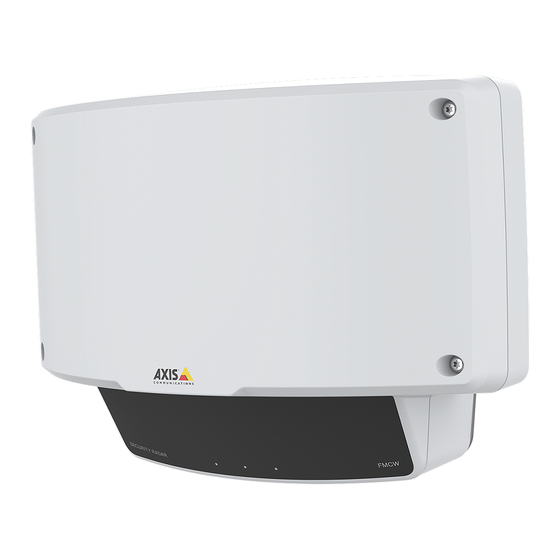
Page 22: Specifications
AXIS D2110-VE Security Radar Specifications Specifications Product overview Control button Network LED Status LED Power LED PoE out LED microSD card slot Power connector (DC) I/O connector Relay connector 10 Grounding screw 11 Network connector (PoE in) 12 Network connector (PoE out) 13 Intrusion alarm sensor For technical specifications, see Specifications on page 22. -
Page 23: Sd Card Slot
• Resetting the product to factory default settings. See page 18. • Connecting to an AXIS Video Hosting System service. See . To connect, press and hold the button for about 3 seconds until the Status LED flashes green. Connectors Network connector RJ45 Ethernet connector with Power over Ethernet Plus (PoE+). - Page 24 AXIS D2110-VE Security Radar Specifications Note Maximum Ethernet cable length is 100 m in total for PoE out and PoE in combined. You can increase it with a PoE extender. I/O connector Use the I/O connector with external devices in combination with, for example, event triggering and alarm notifications. In addition to...
- Page 25 AXIS D2110-VE Security Radar Specifications Power connector 2-pin terminal block for DC power input. Use a Safety Extra Low Voltage (SELV) compliant limited power source (LPS) with either a rated output power limited to ≤100 W or a rated output current limited to ≤5 A.
- Page 26 User Manual Ver. M5.9 AXIS D2110-VE Security Radar Date: January 2022 © Axis Communications AB, 2020 - 2022 Part No. T10145149...
Need help?
Do you have a question about the D2110-VE and is the answer not in the manual?
Questions and answers