
Related Manuals for Zeta Alarm Limited SmartConnect SCM-NM


Summary of Contents for Zeta Alarm Limited SmartConnect SCM-NM
- Page 1 RS485 NETWORK MODULE INSTRUCTION MANUAL SCM-NM DOC: GLT-294-7-13 ISS: 001 DATE: 10.02.2021...
- Page 2 RS485 NETWORK MODULE INSTRUCTION MANUAL General The Smart Connect Multi-loop system network has the facility to monitor, indicate and control the functions of a fire alarm installation, thus allowing signals to be distributed around a large site. The network will accommodate up to 64 nodes.
- Page 3 RS485 NETWORK MODULE INSTRUCTION MANUAL TRM RJ45 Port Address Designation Each RJ45 port on the Smart Connect Multi-loop termination has its own unique port address. This port address is important to keep note of as it is displayed on Alarm/Fault messages and is used when configuring or setting up cause and effects on the panel (See SCM operation manual GLT-261-7-11).
- Page 4 RS485 NETWORK MODULE INSTRUCTION MANUAL Power on Procedure 1. After the above has been completed, turn the panel on (Via AC Only). The panel will follow the same power up sequence described in initial power up section above 2. The panel will now display one of the following messages Message Meaning Panel has not detected any modules fitted...
- Page 5 RS485 NETWORK MODULE INSTRUCTION MANUAL Check that the module configuration is as expected using the to navigate the through the port numbers. Press the icon to confirm the changes. The new module is now configured into the panel and is ready for use. Since the batteries are not connected, the panel will report them as removed, lighting the yellow “Fault”...
- Page 6 RS485 NETWORK MODULE INSTRUCTION MANUAL Ring Topology NOTE: It is recommended to install the network in a ring topology for protection against open circuit and short circuit faults. NOTE: Star topology not supported Wiring recommendations The Smart Connect Multi-loop network can support up to 64 panels. Maximum distance between nodes:- *100M using standard fireproof cable 1KM using a screened data cable RECOMMENDED CABLE: Belden type Screened twisted pair...
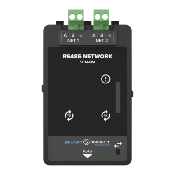
- Page 7 RS485 NETWORK MODULE INSTRUCTION MANUAL Front Unit LED Indications LED Indication Description LED Indication Description Flashing yellow when a fault on the Flashing green when the RS485 is RS485 circuit is detected. receiving information. Pulses to show communication Flashing green when the RS485 is between the module and the transmitting information.
Need help?
Do you have a question about the SmartConnect SCM-NM and is the answer not in the manual?
Questions and answers