
Subscribe to Our Youtube Channel
Related Manuals for DURAVANT Wulftec WCA-SMART

Summary of Contents for DURAVANT Wulftec WCA-SMART
- Page 1 User Reference Guide to WCA-SMART Wulftec Equipment SO #160831-1 Emhart Teknologies - Stanley P a g e...
- Page 3 User Reference Guide to Wulftec Equipment WCA-SMART ………………………………………… A technical publication of Wulftec International Inc. © 2013 Wulftec International Inc. All rights reserved Published by: Wulftec International Inc. 209 Wulftec Ayer’s Cliff (Quebec) Canada J0B 1C0 Author: Wulftec International Inc. / GP Copyrights ©...
-
Page 4: Table Of Contents
TABLE OF CONTENTS Wulftec – A tradition of Strength............................. 5 Warranty ..................................6 Introduction ..................................7 Safety Instructions ................................8 Inspection ..................................9 Safety Labels ................................13 Installation ..................................15 Glossary ..................................21 Main Components – WCA-SMART ..........................22 Machine Assemblies ..............................23 Modes of Operation .............................. -
Page 5: Wulftec - A Tradition Of Strength
Canadian-U.S. border and 75 miles from Montreal. We take pride in knowing that our commitment to excellence just can’t be beat. Wulftec is a member of the DURAVANT family of companies. Duravant is a global engineered equipment company with manufacturing, sales and service facilities throughout North America, Europe and Asia. Through their portfolio of operating companies, Duravant delivers trusted end-to-end process solutions for customers and partners through engineering and integration expertise, project management and operational excellence. -
Page 6: Warranty
WARRANTY All parts on stretchwrappers manufactured by Wulftec International Inc. (hereinafter called “Wulftec”) are warranted to be free of manufacturing defects for a period of three (3) years from the date of shipment, if installed, maintained and used in accordance with factory specifications except for the two (2) blue polyurethane coated rollers whose coating carry a lifetime warranty and the 25”... -
Page 7: Introduction
INTRODUCTION The purpose of your Wulftec equipment is to wrap palletized loads with stretch film or netting using various modifiable wrap parameters. Importance of the Manual This user reference guide, included with the machine, contains mechanical drawings, electrical schematics as well as a CD containing the machine programs and drive parameter settings. -
Page 8: Safety Instructions
SAFETY INSTRUCTIONS Read Carefully Before Operating Any Wulftec Machinery Wulftec stretch wrap machinery should be handled with the same caution and care as with any other industrial equipment. Many automatic functions may be potentially hazardous. For this reason, except for the authorized operator(s) and maintenance crew, other personnel should keep clear at all times. -
Page 9: Inspection
INSPECTION TRANSPORT INSPECTION Immediately upon arrival, visually inspect machine for damages caused in transport. If damage to the machine has occurred, it must be reported to the freight carrier immediately and Wulftec should be notified. As stated in the warranty, Wulftec is not responsible for damage caused in transit. If no damage is apparent, carefully remove all wrapping material, strapping, blocks, etc. - Page 10 GENERAL SAFETY The wrapper has been built in compliance with the presently valid technical rules and is reliable in operation. It has been submitted to a final test on the functionality of components, protections, controls and emergencies. However, dangers may still arise from this machine if it is inappropriately used by untrained personnel or if it is used for purposes it is not intended for.
- Page 11 PERSONAL SAFETY It is mandatory to respect the following personal safety guidelines to prevent all types of injuries (minor to fatal). Use the E-Stop button if stopping machine movement (wrapper/conveyor) rapidly is necessary. Never try to stop or hold a pallet while it is in movement on the conveyor line or on a turntable. Never use or service the machine without proper safety protections (deactivated or absent).
- Page 12 PERSONNEL The wrapper must only be operated and serviced by authorized, trained and instructed personnel. Instructed personnel consists of persons who have been informed about their work and the dangers that may possibly arise in case of inappropriate behavior and who have been trained, as far as this was necessary, and instructed about all necessary safety installations and safety measures.
-
Page 13: Safety Labels
SAFETY LABELS In an effort to reduce the risk of injury to personnel working with or around Wulftec equipments, safety labels are placed at various important points to alert workers of potential hazards. Please check equipment and note all safety labels. - Page 14 MOVING MACHINERY For the transport of the packed or partly packed machine to the place of installation within your facility, an overhead crane, a forklift truck or any other suitable lifting gear may be used. Only use lifting gear of sufficient load bearing capacity! ...
-
Page 15: Installation
INSTALLATION To install the machine is to unwrap, erect and position structures, align, level and position all conveyors according to the machine’s layout drawing specifications and install any options the equipment could have. Install all junction boxes and liquid tight wire runs under the conveyors. Make sure all sensors and quick plugs are properly connected. Hook-up necessary communication signals, required electrical power (always done by an electrician) and air supply. - Page 16 INSTALLATION (CONT’D) Important! Refer to mechanical layout to make sure you have the proper measurements or information regarding the machine since machine height, conveyor positioning and control panel location have already been pre-determined by Wulftec according to the specifications received. Make sure machine is placed on a level surface before and after unpacking and that machine structure is level as well once placed in position.
- Page 17 INSTALLATION (CONT’D) 13. Plug in pneumatic components to air supply. Make sure CFM and PSI are appropriate (refer to mechanical drawings). 14. At this point, if the necessary wires for the communication signals have been pulled, plug them in the proper terminals according to the electrical schematics, prior to moving on with the start-up procedure.
- Page 18 INSTALLATION OF IN-LINE TOP SHEET For the position of the top sheet over the conveyor, please refer to drawing below. Make sure the top sheet autoheight photoeye is aligned with the previous conveyor and the entrance photoeye is aligned on the top sheet conveyor.
- Page 19 INSTALLATION OF IN-LINE TOP SHEET Remove the top sheet head and put it on 4X4 on the floor Install the first top sheet leg to the top sheet head. The leg with the junction box and control box with the E-stop goes on the motor side facing the outside (B) Install the second leg Put the 3 bolts, locks and nuts to hold the legs.
- Page 20 INSTALLATION OF FENCE HANDLE Refer to the mechanical drawings in order to facilitate the installation of the handle on the safety fencing. INSTALLATION OF LIGHT CURTAIN The light curtains must be installed at the end of a conveyor, away from the wrap zone and be positioned as close to the conveyor side as possible (refer to overview drawing).
-
Page 21: Glossary
GLOSSARY Analog sensor: Supplies a proportional signal corresponding to the distance from the target to the sensor face. Autoheight: A feature characterized by a photoeye constantly monitoring the height of the carriage in relation with the height of the load being wrapped. The optical sensor detects when the carriage has reached proper height and gives the signal to the PLC to stop the carriage. -
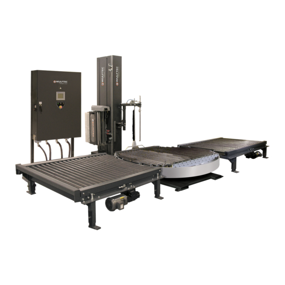
Page 22: Main Components - Wca-Smart
MAIN COMPONENTS – WCA-SMART Enclosure / control panel Cut wire and wipe system Film Clamp Conveyor line Carriage (film delivery system) Turntable / Ring gear support / drive system P a g e | 22... -
Page 23: Machine Assemblies
MACHINE ASSEMBLIES Enclosure/Control Panel This enclosure/control panel is the “heart” of the machine. All machine controls are located inside the enclosure: HMI, PLC, drives, relays, contactors, etc. Cut and Wipe Arm: Installed in front of the tower, this assembly is used to cut the film after the wrapping is done. It also wipes the film tail on the load’s surface. -
Page 24: Modes Of Operation
MODES OF OPERATION START/AUTOMATIC MODE The system can be put in start (run) mode by pressing and releasing the “START/STOP” push button when the button is blinking. Whenever the light is lit solid (green light) means the system is in running mode. STOP MODE The system can be put in stop mode by pressing and releasing the “START/STOP”... -
Page 25: Controls
CONTROLS Controls and Functions Main Power Switch Turns the power On/Off to the machine. Power Light Illuminates to indicate power On/Off. Rearm / Acknowledge Alarm Used to rearm the master control relays (fence doors and e-stops), clear drive faults and acknowledge alarms. Start Mode (light) The start mode light is lit solid when machine is in start mode (automatic). - Page 26 AUTOMATIC PAGE This page is the most frequently used during machine operation. A “local message display” informs on what steps to take in order to put the system back in operation. It also displays the action or state of all machine zones. The small screen section just above is the alarm banner, which will pop up whenever the machine encounters a problem.
- Page 27 WRAP PATTERN PAGE Password Level 1 Controls Functions Pattern Number & Description Used to select a pattern number and allows the modification of its description and settings. Wrapping Mode/Bypass Mode When selector is set to bypass mode, the load will pass through the wrapping zone without being wrapped.
- Page 28 WRAPPING SETTINGS PAGE Password Level 1 Controls Functions Rotation Speed This allows the rotation to be set at the speed best suited to the load, up to a maximum allowed by the wrapper. If used to slow down machine speed during operation, reduce slowly.
- Page 29 WRAPPING SETTINGS PAGE (CONT’D) Password Level 1 Controls Functions Time Before Feed Used to select time of plastic feeding at the beginning of the load. Feed after Load Used to select time of plastic feeding at the end of the load. Feed after Cut Used to select time of plastic feeding after the cut.
- Page 30 FILM TENSIONS PAGE Password Level 1 Controls Functions Start Wrap Film Tension Used to set the film tension to be applied at the beginning of the cycle. Top/Bottom Wrap Film Tension Used to set the tension of the film to be applied to the top and bottom of the load (separate values).
- Page 31 FILM ROLL SETTINGS PAGE Password Level 2 Controls Functions Edit Film Roll 1/2 Press this button to edit film roll information. Film Roll Length Enter the film roll length (new, unused roll). Film Roll Weight Enter the film roll weight (new, unused roll). Film Gauge Enter the film gauge (current roll).
- Page 32 OTHER SETTINGS PAGE Password Level 1 Controls Functions Low Load Pattern Used to set the default pattern to be used with low loads. Waiting Time on 1 Outfeed Used to set the time during which the machine will pause to allow for load weighing.
- Page 33 ADVANCED SETTINGS PAGE Password Level 2 Controls Functions Autoheight Allows the autoheight sensing for pallet load height variations. (There are Off/On two limit switches on the carriage with adjustable stops on the vertical boom as safety override). When the switch is at OFF, the system will look at the top limit switch instead.
- Page 34 IN LINE TOP SHEET SETTINGS PAGE Password Level 1 Controls Functions Wait Rotation On/Off Used to activate or deactivate the wait rotation. When activated, the top sheet will wait for the wrap cycle to be completed before receiving a new load Auto Bypass On/Off Used to activate or deactivate the top sheet automatic bypass.
- Page 35 WRAPPER MANUAL PAGE Controls Functions Local Message Display Displays the status of the machine component selected. This display will appear if an interlock is present. Carriage Manual Speed Used to set the speed of the carriage, in Hz, in manual mode. Carriage Used for the carriage vertical movement.
- Page 36 WRAPPER MANUAL PAGE (CONT’D) Controls Functions Top Sheet Used for the top sheet vertical movement. Use the multi-function switch on the control panel to move the top sheet. Top Sheet Roll Used for the top sheet roll movement. Use the multi-function switch on the control panel to rotate the top sheet roll.
- Page 37 DATE AND TIME SETTINGS PAGE Controls Functions Set Date and Time Used to set the date and time displayed on the HMI. Shift Schedule This page represents the start and end time of the plant’s three shifts (day, evening and night). Just enter the time for the three shifts’ schedule. P a g e | 37...
- Page 38 SAVE AND RESTORE SETTINGS PAGE Password Level 2 Controls Functions Restore Buttons (Wulftec) Press the desired button in order to restore the default settings. Restore Buttons (Customer) Press the desired button in order to restore the settings that were last saved using the Save buttons displayed here.
- Page 39 PASSWORD PAGE Password Level 1 Controls Functions Add User / Group Press to add users / group. Delete User / Group Press to delete users / group. Modify Group Membership Press to define users/ group accesses. Change User Properties Press to change the password for a selected user or group of users. P a g e | 39...
- Page 40 SHIFT STATISTICS PAGE Controls Functions This screen shows the performance information for the current day’ shifts, and up to two days before (in different screens). Load(s) Wrapped For each shift, indicates the number of loads wrapped. Load(s) Passthrough For each shift, indicates the number of loads that have passed through unwrapped.
- Page 41 PERFORMANCE PAGE Controls Functions Actual R.P.M. Indicates the machine R.P.M. from the last cycle completed. Number of Turns in Last Indicates the number of turns (wrap layers) done during the last cycle Cycle completed. Actual Rotation Position Displays the actual rotation position by indicating the current tooth. P a g e | 41...
- Page 42 PERFORMANCE PAGE Controls Functions Conveyor Time For Loads Press this button to set the time needed for the load to go through the Per Hour wrapping conveyor (this time will be added to the wrap cycle time to calculate the amount of loads per hour). P a g e | 42...
- Page 43 PERFORMANCE PAGE Controls Functions Cycle Counter Counts the amount of wrapping cycles since the machine was first started. Pallet Counter Counts the amount of pallets wrapped and unwrapped since the machine was first started. Hour Counter Counts the amount of hours of operation since the machine was first started. (Resettable) Cycle Counter Counts the amount of wrapping cycles since the last reset.
- Page 44 ALARM PAGE Controls Functions Alarm Log Lists the alarms of the machine, including the date and time the error occurred. Alarm Banner Displays the alarm of the machine. To acknowledge the alarm(s), press Acknowledge Alarm or Acknowledge All Alarms. *Silence Alarm Used to stop the alarm buzzer.
- Page 45 MAINTENANCE PAGE Password Level 2 to access ACK Maint. button Controls Functions Maintenance Log Active / The maintenance log active lists the current maintenance that remains to be History carried out. maintenance history lists completed acknowledged maintenances of the machine. Alarm Banner Displays the alarm of the machine.
- Page 46 REAL TIME FILM MONITORING PAGE Controls Functions ### Pallets Wrapped on Displays the number of pallets wrapped using the current film roll. Current Roll ### Pallets Wrapped During Displays the number of pallets wrapped during the current shift. Current Shift Estimated Pallets Remaining Displays the number of pallets that can be wrapped with the film left in the to be Wrapped With Current...
- Page 47 REAL TIME FILM MONITORING PAGE Controls Functions For the last 30 pallets wrapped, this display indicates: Pallet Monitoring Using the arrows, the operator can navigate through the last 30 pallets wrapped in order to obtain the following information: Cycle ## /30 (Pattern #: ##) Indicates the selected cycle and the wrap pattern that was used for this pallet.
-
Page 48: Component Adjustments
COMPONENT ADJUSTMENTS The physical components of the machine must be adjusted for optimal machine operation. CARRIAGE DOOR PROXIMITY SENSOR ADJUSTMENT First, ensure the proximity sensor lights up when the door is fully locked in position. When the door is fully closed the latch will be parallel with the carriage top plate. - Page 49 ANALOG SENSOR ADJUSTMENT The following steps accomplish replacement or adjustment of analog sensor and cam: Activate the emergency stop. Remove the film roll. Remove the carriage cover. Make sure that the dancer bar is completely retracted and at home position. Using a ruler, align the right side of the cam with the edge of the analog sensor bracket (A).
- Page 50 PHOTOEYE ADJUSTMENT (DIFFUSE) Standard direction of the material being scanned LED signal strength indicator Optical axis sender Sensing range adjustment Optical axis receiver Mounting hole Ø 5.2mm LED indicator green: power on LED indicator yellow: status of received light beam Adjustment of scanning distance: double teach button Diffuse Photoeye (standard and conveyor) LED Indicators: Each sensor features two LED indicators to help you program and use the sensor.
- Page 51 PHOTOEYE ADJUSTMENT (RETROFLECTIVE) Optical axis sender Optical axis receiver Mounting hole Ø 5.2mm LED indicator green: power on LED indicator yellow: status of received light beam Retroflective Photoeye LED Indicators - Each sensor features two LED indicators to help you program and use the sensor. Green - The green LED indicates “power”.
- Page 52 PHOTOEYE ADJUSTMENT (DARK LOAD / LASER) Potentiometer Dark Load Photoeye Potentiometer – This is used to adjust the photoeye sensitivity. P a g e | 52...
- Page 53 CARRIAGE LIMIT SWITCH ACTIVATOR BLOCK ADJUSTMENT 1: The limit switch activator dead bolt (A) is factory installed and should never be altered. It is positioned at the carriage’s lowest possible position. 2: This limit switch activator block (B) can slide up and down to stop the carriage. Typically the bottom one is resting against the dead bolt (A) so that the machine can wrap as low as possible;...
- Page 54 CUT & WIPE ARM REED SWITCH ADJUSTMENT 1-Adjust the (RETRACTED) proximity sensor so that the signal is ON when the cut & wipe arm is fully retracted. 2-Adjust the (EXTENDED) reed switch so that the signal is ON approximately when the arm is in line with the corner of the load (centered with the clamp) as shown in the drawing below.
- Page 55 SPRING LOADED GATE ADJUSTMENT Verify if the gate’s middle roller is parallel with the two (2) pre-stretch rollers. If it is not parallel, adjust using the springs located on top and bottom of the carriage gate. The tighter the springs, the force applied on the pre-stretch rollers will be reduced. If the force on the spring-loaded roller needs to be augmented, just loosen the springs using the bottom and top screws on the carriage gate.
-
Page 56: Mode Of Operation - Standard
MODE OF OPERATION - STANDARD NOTE: You can temporarily stop the wrapping sequence at any time. This can be done by pressing the Start/Stop button and following steps on HMI (or press E-Stop button in case of emergency - to re-start the wrap cycle after an emergency stop, simply release the E-Stop button and follow steps on HMI). -
Page 57: Mode Of Operation - In-Line Top Sheet
MODE OF OPERATION – IN-LINE TOP SHEET NOTE: You can temporarily stop the wrapping sequence at any time. This can be done by pressing the Start/Stop button and following steps on HMI (or press E-Stop button in case of emergency - to re-start the wrap cycle after an emergency stop, simply release the E-Stop button and follow steps on HMI). -
Page 58: Film Loading
FILM LOADING The film roll should be loaded so that the tacky surface will face inward on the pallet load. Make sure the machine is in stop mode before opening the fencing door. Open safety fencing door. Push the lock on the carriage gate latch to unlock carriage door. Remove empty film roll. - Page 59 FILM LOADING (CONT’D) WARNING! Always ensure that the machine is in stop mode before attempting to thread the film carriage. Inadvertent movement of the dancer bar will cause the rollers to turn abruptly, creating the possibility of serious injury. The operator must respect the film loading and threading instructions AT ALL TIMES! If the film web breaks during the cycle, reattach the film, or if necessary, rethread the film following the instructions.
-
Page 60: In-Line Top Sheet Film Loading
IN-LINE TOP SHEET FILM LOADING Unroll plastic so that the plastic supply is at the bottom. Place roll of top sheet on the two rollers. Pull the metal bar with casters and insert the plastic between the casters and the first roller. Make sure the plastic goes down to at least the top sheet clamp and between the flappers. -
Page 61: Clamp Loading Procedure
CLAMP LOADING PROCEDURE 1. The clamp is closed. 2. Open the clamp manually or pneumatically. 3. Place the film between the clamp jaws. 4. Close the clamp jaws manually or pneumatically to keep the film in place. P a g e | 61... -
Page 62: Pre-Stretch Ratios - Chain Driven
PRE-STRETCH RATIOS – CHAIN DRIVEN RATIO % "A" WULFTEC "B" WULFTEC 0MSPK00015 0MSPK00022 50(52.5) 0MSPK00008 0MSPK00015 75(71.4) 0MSPK00008 0MSPK00076 100 (90.5) 0MSPK00008 0MSPK00078 125(122.2) 0MSPK00076 0MSPK00011 0MSPK00015 0MSPK00011 175 (166.8) 0MSPK00015 0MSPK00014 0MSPK00008 0MSPK00011 0MSPK00008 0MSPK00014 0MSPK00016 0MSPK00014 0MSPK00022 0MSPK00014 0MSPK00008 0MSPK00140 0MSPK00022... -
Page 63: Pre-Stretch Ratios - Belt Driven
PRE-STRETCH RATIOS – BELT DRIVEN RATIO % "A" WULFTEC "B" WULFTEC BELT "1" WULFTEC 16 T 0MSPK00131 12 T 0MSPK00168 150L050 0MCHN00044 14 T 0MSPK00130 14 T 0MSPK00130 150L050 0MCHN00044 13 T 0MSPK00132 14 T 0MSPK00130 150L050 0MCHN00044 13 T 0MSPK00132 15 T 0MSPK00124... -
Page 64: Pre-Stretch Ratios - Belt Driven / Premium Efficiency Motor
PRE-STRETCH RATIOS – BELT DRIVEN / PREMIUM EFFICIENCY MOTOR RATIO % "A" WULFTEC "B" WULFTEC BELT "1" WULFTEC 0MSPK00131 0MSPK00168 150L050 0MCHN00044 0MSPK00130 0MSPK00130 150L050 0MCHN00044 0MSPK00132 0MSPK00130 150L050 0MCHN00044 0MSPK00132 0MSPK00124 150L050 0MCHN00044 0MSPK00168 0MSPK00131 150L050 0MCHN00044 0MSPK00130 0MSPK00134 165L050 0MCHN00045 0MSPK00125... -
Page 65: Changing The Pre-Stretch
CHANGING THE PRE-STRETCH Disconnect power to machine. Carry out lock out tag out procedure. Remove carriage cover. Loosen idler sprocket using appropriate wrench. Remove the chain or the belt (located between A and B sprockets) Remove A and B sprockets by loosening the set screws. If necessary, use a puller. Using the pre-stretch chart in the manual, select desired pre-stretch and find appropriate pulley kit (pulley, belt/chain) for the selected pre-stretch. -
Page 66: Maintenance Instructions
MAINTENANCE INSTRUCTIONS Important! Before undertaking maintenance or repair operations, it is mandatory to carry out the proper safety verifications to prevent injuries to personnel or damages to the equipment. The proper safety verifications include selecting the Off button on the main switch and carrying out the tag-out/lock-out procedure. Only the person responsible for the safety verifications should work on the machine. -
Page 67: Fence Entry/Exit Procedure
FENCE ENTRY/EXIT PROCEDURE Please use this procedure when entering and exiting the safety fencing. Make sure the wrapper zone is in stop mode. If not, press Start/Stop push button to put machine in stop mode. Make sure the key-switch green light is off (which indicates that the door is unlocked). Open the fence door. -
Page 68: General Maintenance
GENERAL MAINTENANCE These are the specifications for a standard machine. Please refer to the mechanical layout and electrical schematics for your exact machine specifications. -Electrical: 230Vac/3 phase/60Hz – 13 Amps -Pneumatic: 3CFM @ 80PSI - clean dry air -Lube station grease (Ring gear bearing): Unirex EP2, Esso or equivalent -Pinion and ring gear teeth grease: Unirex EP2, Esso or equivalent -Reducer oil: Mobil Glygoyle 460 -Chain grease: Unirex EP2, Esso or equivalent... - Page 69 REDUCERS The reducers on your equipment are filled with Mobil Glygoyle 460 oil. Do not mix different lubricants in the reducer. Lubricant incompatibility may result in premature failure. Do not use Mobil Glygoyle 460 oil if your operating environment requires a different type of oil (ex. cold temperature environment) or if you have requested a different type of oil in your system.
- Page 70 REDUCER CHART Legend: F = Refill Plug V = Vent Plug L = Level Plug D = Drain Plug P a g e | 70...
- Page 71 PHOTOEYES Cleaning: Periodicity will be determined in relation with the type of environment in which the machine is installed. It is important to clean the face of each photoeye and reflector every 2000 hours of operation to get rid of any material that could induce bad readings.
- Page 72 CARRIAGE MAINTENANCE PRE-STRETCH BELT / CHAIN ADJUSTMENT The pre-stretch belts should be checked for proper tension every 2000 hours of operation. Recommended tension is 1/64” deflection per inch of belt span with a force of approximately 25 lbs. The motor drive belt is adjusted by loosening the four (4) motor mounting bolts and sliding the motor in the mounting slots.
- Page 73 CARRIAGE BEARINGS Verify for radial, an axial movement of the inner race. When movement is more than 1/32in, replace all four bearings. Pre-stretch roller bearings CARRIAGE TROLLEY Chain tensioners (1 on each chain) Wheels (4 in all) Adjustable carriage trolley P a g e | 73...
- Page 74 CARRIAGE TROLLEY CHAINS Tension needs to be at 0.025in/feet @ 25lbs. Position the carriage to the center of the travel limits. Hold the locknut while tightening the tension-adjusting nut on the "upper" section. (The lower section is for aligning the v- groove/carriage mounting plates).
- Page 75 RING GEAR Slip ring PINION-RING GEAR Remove the ring gear cover and wipe the accumulated grease. Measure the backlash between the pinion and ring gear, it should not exceed 0.010in and nominally, the backlash should be at 0.005 in. Beware that a ring gear is not perfectly round.
- Page 76 LUBE STATION The greaser is controlled by a PLC output and should be greasing for 60 seconds after a specific number of hours. The number of hours between lubrications is factory set according to multiple factors. Inspect the grease container of the lube station once a month and refill with EP2 grease as recommended by Wulftec unless you have requested a different type of grease in your system (ex.
-
Page 77: Preventive Maintenance Calendar
PREVENTIVE MAINTENANCE CALENDAR Preventive maintenance periodicity will be determined in relation with the type of environment in which the machine is installed and used. Daily preventive maintenance requires the operator to verify that no obstacles and no danger hazards are present around the machine. WEEKLY MAINTENANCE Frequency Operation... -
Page 78: Maintenance Log
MAINTENANCE LOG List of maintenance and/or repair operations carried out on the machine. Date Description of operation P a g e | 78... -
Page 79: Troubleshooting Alarms
TROUBLESHOOTING ALARMS Alarm Problem Solution Emergency stop At system power up you will have this Release all E-stop push buttons and re-arm pressed message and it will also appear when an the E-stop loop by pressing on the rearm E-stop button is pressed push button Safety fence door Each time the fence door is opened, you... - Page 80 TROUBLESHOOTING ALARMS Alarm Problem Solution Rotation not at home The system is in start mode and the Press the start/stop push button to initialize position rotation is out of home position or when the system. Verify air brake operation, the home position sensor is defective home position prox.
- Page 81 TROUBLESHOOTING ALARMS Alarm Problem Solution Pop up raise /lower The pop up is commended to go up or First try the machine in manual mode. motion problem down and does not reach its position Then, verify that the air supply is present. within 15 seconds Verify the «lowered pop up position»...
-
Page 82: Parts Reference
PARTS REFERENCE OW TO USE THE FOLLOWING SECTION Our systems have been designed and built to offer our customers reliable machine operation for years to come. When the time comes to order spare parts or replacement parts, this section will help you pinpoint the information you need to order parts through your distributor.
Need help?
Do you have a question about the Wulftec WCA-SMART and is the answer not in the manual?
Questions and answers