Table of Contents
Advertisement
Quick Links
AstroLink 4 mini II manual - @2021 astrojolo.com
AstroLink 4 mini II
astrojolo.com @2021
WARNING!
Do not connect or disconnect stepper motor when power is on. It may
damage stepper motor controller.
Make sure the stepper hold torque is set to 0% before replacing stepper
motor with motor of different type.
1
Rev. 1.0
Advertisement
Table of Contents

Related Manuals for astrojolo AstroLink 4 mini II


Summary of Contents for astrojolo AstroLink 4 mini II
- Page 1 AstroLink 4 mini II manual - @2021 astrojolo.com AstroLink 4 mini II astrojolo.com @2021 WARNING! Do not connect or disconnect stepper motor when power is on. It may damage stepper motor controller. Make sure the stepper hold torque is set to 0% before replacing stepper motor with motor of different type.
-
Page 2: Main Features
AstroLink 4 mini II manual - @2021 astrojolo.com Main features: • Two focuser motor control for Robofocus, Moonlite, or generic unipolar or bipolar stepper motor • 1/8 and 1/32 micro-stepping control with 2.0A maximum current and 1.4A maximum continuous hold current •... -
Page 3: Device Overview
Sensors AstroLink 4 mini II has two equivalent sensor inputs, so you can plug any available sensor into any socket and it will be recognized and properly assigned. Connecting three sensors (two temperature/humidity and one sky temperature) requires an additional sensor bus splitter. Sensor readings are available in the dedicated panel software and via ASCOM Observing Conditions and INDI interfaces. -
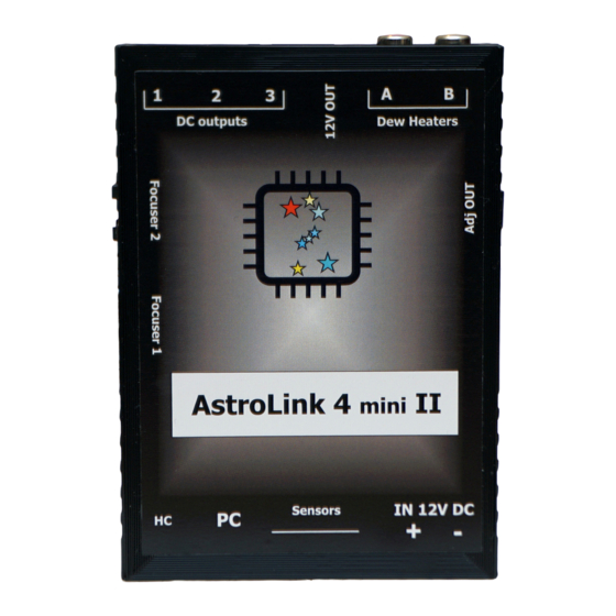
Page 4: External View
AstroLink 4 mini II manual - @2021 astrojolo.com External view 1. AUX input 6. Focuser 1 output 2. USB 2.0 input 7. Adjustable voltage output 3. Sensors inputs 8. Heaters outputs 4. 12V DC input 9. 12V permanent output 5. Focuser 2 output 10. -
Page 5: Panel Overview
AstroLink 4 mini II manual - @2021 astrojolo.com Panel overview AstroLink 4 mini II panel contains several control sections. Most of the area is occupied by different controller sections, which will be described later on. Below the control section, several other controls are available. -
Page 6: Charts And Notes
AstroLink device is connected. This driver is for all members of the AstroLink 4 family, that is why you also need to select a specific device – AstroLink 4 mini II in this case. You can also test the connection using the Test port button. -
Page 7: Connection Status
AstroLink 4 mini II manual - @2021 astrojolo.com There are two more tabs available for the ASCOM driver. There you can adjust sky temperature cloud coverage mapping points that correspond to clear sky and maximum cloud coverage, and set names for DC and PWM outputs that will be visible in ASCOM Switch client software. -
Page 8: Focuser Section
AstroLink 4 mini II manual - @2021 astrojolo.com Focuser section The focuser position in mm is calculated based on the focuser position in steps and step size defined in settings. The coarse relative movement factor can be set in settings between 2 and 10. - Page 9 Motor current [mA] – this is the current limit set to the motor. Refer to your motor technical data to set proper current. For 12V unipolar geared motors offered in shop.astrojolo.com set it to 400mA or use preset.
-
Page 10: Pwm Section
AstroLink 4 mini II manual - @2021 astrojolo.com PWM section PWM output value can be set between 0 and 100%. HEAT option controls value automatically based on current relative humidity. AUTO option controls value automatically to keep Sensor #2 at a given temperature. -
Page 11: Power Section
AstroLink 4 mini II manual - @2021 astrojolo.com Power section The power section helps to monitor power conditions. It displays voltage, current, and energy consumption. Under the settings button, there are some more options related to alerts and protection. Input voltage - this field displays the current supply voltage value Regulated voltage –... - Page 12 AstroLink 4 mini II manual - @2021 astrojolo.com also buzz with device buzzer - when one or more alerts is triggered there will be a sound signal emitted from the AstroLink device also alert with system sound - when one or more alerts is triggered there will be a system sound alert...
-
Page 13: Sensors Section
AstroLink 4 mini II manual - @2021 astrojolo.com Sensors section Sensors and PWM sections are separate ones, although they work together to provide some combined functionalities. The sensors section contains four read-only fields that labels may be changed. Sensor sockets in AstroLink are equivalent, so it does not matter where you connect the given sensor. - Page 14 AstroLink 4 mini II manual - @2021 astrojolo.com In the tab called Alerts you can set temperature change monitor parameters: Enable temperature alert - here you can enable or disable temperature alerts Temp. change sensor - it is the sensor that temperature is taken to monitor its value. Make sure the selected sensor is connected to the device Temp.
-
Page 15: 12V Output Section
AstroLink 4 mini II manual - @2021 astrojolo.com 12V output section The second section is called the 12V output. Here we have three check-boxes that control DC outputs where you can connect supply voltage to peripheral devices like mounts, cameras, or filter wheels. -
Page 16: Astrolink Charts
AstroLink 4 mini II manual - @2021 astrojolo.com AstroLink charts AstroLink charts are the tool that allows you to monitor the following data that is collected by the AstroLink device: • temperature, humidity, and dewpoint measured by connected sensors •... - Page 17 AstroLink 4 mini II manual - @2021 astrojolo.com • Export as image - this option saves the current graph as a PNG image in the folder selected by the user in the dialog. The saved image will contain exactly what is visible on the chart •...
-
Page 18: Overcurrent And Overvoltage Protection
AstroLink 4 mini II manual - @2021 astrojolo.com Overcurrent and overvoltage protection AstroLink panel contains settings to provide overcurrent and overvoltage protection. Both input voltage and total output current are monitored 200 times per second and measured values are compared to user settings. If any of these values exceeds settings for some specified time (also configured by the user) then all PWM and DC outputs will be switched off. -
Page 19: Temperature Compensation
AstroLink 4 mini II manual - @2021 astrojolo.com Temperature compensation Temperature compensation in AstroLink 4 mini II is implemented linearly. So there is only one parameter that describes how temperature affects the focus point. It is not a perfect approach, however, its accuracy is good enough for most amateur setups. - Page 20 AstroLink 4 mini II manual - @2021 astrojolo.com compensation amount will exceed the threshold value. You need to adjust this threshold value in the script according to your setup specifications, in a similar way to the Auto compensation threshold described before You can save the script to the file with a VBS extension (astrolink-compensate.vbs for example), so it...
-
Page 21: Compensation Calculator
AstroLink 4 mini II manual - @2021 astrojolo.com Compensation calculator A compensation calculator is a simple tool that can be used to calculate the compensation coefficient basing on temperature and focuser position points read from the AstroLink panel. The compensation calculator can be found in the bottom left menu. - Page 22 AstroLink 4 mini II manual - @2021 astrojolo.com If one or two points are incorrect, and all others fit straight line nicely, then these bad points may be a result of a mistake and can be removed from the data point set. You need to select them in the data table and remove them using the Delete key.
- Page 23 AstroLink 4 mini II manual - @2021 astrojolo.com set of data points during another imaging session. If the new points will still indicate such behavior, then probably the setup you use cannot be set for compensation: You need to enter data points collected with one filter only! There can be a focus shift between different filters, and the calculated coefficient may not be accurate.
-
Page 24: Ground Loops
AstroLink 4 mini II manual - @2021 astrojolo.com Ground loops The ground loop in the electrical system occurs when two points that should have the same potential have different voltages. The ground loop in the astroimaging setup may occur when the ground (i.e. -
Page 25: Scripting Support
AstroLink 4 mini II manual - @2021 astrojolo.com Scripting support You can also control the AstroLink 4 mini II device using scripts to automate the acquisition process. All ASCOM interfaces are available and can be controlled from the script. You can find a simple script example in the Temperature compensation section. -
Page 26: Troubleshooting
AstroLink 4 mini II manual - @2021 astrojolo.com Troubleshooting AstroLink log files All AstroLink log files are created in the My Documents/AstroLink folder. Files that name contains only the current date are data collections from AstroLink charts and can be imported to any other software (like MS Excel) for further processing. -
Page 27: The Sensor Is Not Recognized - No Value Is Read
AstroLink 4 mini II manual - @2021 astrojolo.com The sensor is not recognized - no value is read Disconnect the device, turn off the power, plug out and plug in sensor and reconnect power and AstroLink panel Some fields in AstroLink panel software are red and there are window system sound and device beeps One or more alert levels have been exceeded. -
Page 28: Access Denied To Com Port When Using Ascom Driver
2. restart the computer 3. uninstall the driver 4. restart the computer 5. open ASCOM Profile Explorer and look for “astrolink” or “astrojolo” related items in the Focuser, Observing conditions, and Switch branches. Remove them if found (right-click – delete) 6. -
Page 29: Connections
AstroLink 4 mini II manual - @2021 astrojolo.com Connections Power input Stepper motor output FOCUSER 2 - RJ12 SOCKET FOCUSER 1 – DB9 SOCKET 1, 2 – +12V 1, 2 – coil A 3, 4 – COIL A 3, 4 – coil B 5, 6 –... -
Page 30: Third-Party Software
ASCOM Observing Conditions can be connected to ASTROJOLO Observing Conditions interface (SGPro, N.I.N.A.) In the image below – AstroLink 4 mini II is connected to the panel software, focuser, and switch are connected to Maxim and N.I.N.A software at the same time. -
Page 31: Software And Firmware Update
AstroLink 4 mini II manual - @2021 astrojolo.com Software and firmware update The new software version can be found at https://shop.astrojolo.com/astrolink/ page. There are two software components: AstroLink ASCOM Local Server driver and AstroLink Panel. To update the software you need to: •... -
Page 32: Table Of Contents
AstroLink 4 mini II manual - @2021 astrojolo.com Spis treści Main features: ............................2 Technical data ............................2 Device overview ............................3 PWM outputs ............................3 Switchable 12V DC outputs ......................... 3 Focusing motors control ........................3 Permanent 12V DC output ........................3 Adjustable DC output .......................... - Page 33 AstroLink 4 mini II manual - @2021 astrojolo.com Scenario one ............................24 Scenario two ............................24 Scripting support ........................... 25 Troubleshooting ............................ 26 AstroLink log files ..........................26 AstroLink device does not beep after connecting to the power supply ........... 26 AstroLink device is not recognized by the system after connecting to the computer - no COM port visible ..............................
Need help?
Do you have a question about the AstroLink 4 mini II and is the answer not in the manual?
Questions and answers