Table of Contents
Advertisement
Quick Links
AstroLink 4 USB manual - @2021 astrojolo.com
AstroLink 4 USB
astrojolo.com @2021
WARNING!
Do not connect or disconnect stepper motor when power is on. It may
damage stepper motor controller.
Make sure the stepper hold torque is set to 0% before replacing stepper
motor with motor of different type.
1
Rev. 1.3
Advertisement
Table of Contents

Related Manuals for astrojolo AstroLink 4 USB

Summary of Contents for astrojolo AstroLink 4 USB
- Page 1 AstroLink 4 USB manual - @2021 astrojolo.com AstroLink 4 USB astrojolo.com @2021 WARNING! Do not connect or disconnect stepper motor when power is on. It may damage stepper motor controller. Make sure the stepper hold torque is set to 0% before replacing stepper motor with motor of different type.
-
Page 2: Main Features
AstroLink 4 USB manual - @2021 astrojolo.com Main features: • focuser motor control for Robofocus, Moonlite, or generic unipolar or bipolar stepper motor • 1/8 and 1/32 micro-stepping control with 1.5A maximum current • advanced temperature compensation with scripting support and compensation calculator •... -
Page 3: Device Overview
5V. Sensors AstroLink 4 USB has two equivalent sensor inputs, so you can plug any available sensor into any socket and it will be recognized and properly assigned. Connecting three sensors (two temperature/humidity and one sky temperature) requires an additional sensor bus splitter. -
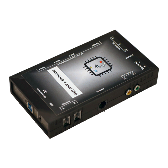
Page 4: External View
AstroLink 4 USB manual - @2021 astrojolo.com External view Rev. 1.3... - Page 5 AstroLink 4 USB manual - @2021 astrojolo.com 1. 12V DC input – XT60 socket 6. LED indicator 2. 12V DC permanent output 7. USB3.0 input optoisolated from analog 3. 12V DC switchable outputs 8. AUX input 4. 5V DC regulated output galvanically 9.
-
Page 6: Panel Overview
AstroLink 4 USB manual - @2021 astrojolo.com Panel overview AstroLink 4 panel contains several control sections. Most of the area is occupied by different controller sections, which will be described later on. Below the control section, several other controls are available. -
Page 7: Status Bar
AstroLink device is connected. This driver is for all members of the AstroLink 4 family, that is why you also need to select connection speed. For AstroLink 4 USB it is 38400 bps. You can also test the Rev. 1.3... -
Page 8: Connection Status
AstroLink 4 USB manual - @2021 astrojolo.com connection using the Test port button. When the trace check-box is checked ASCOM log file will be written with all communication between the device and any software - it can be useful to investigate errors. -
Page 9: Focuser Section
AstroLink 4 USB manual - @2021 astrojolo.com Focuser section The focuser position in mm is calculated based on the focuser position in steps and step size defined in settings. The coarse relative movement factor can be set in settings between 2 and 10. - Page 10 5 for this purpose, so it is possible to do small manual corrections. Motor current [A] – this is the current limit set to the motor. Refer to your motor technical data to set proper current. For 12V unipolar geared motors offered in shop.astrojolo.com set it to 0.4A or use preset.
- Page 11 AstroLink 4 USB manual - @2021 astrojolo.com Set focuser position - you can set any desired focuser position to calibrate it. Usually, it will be used to set a zero position. For this case you need to move the focuser tube inwards as much as possible, then enter 0 value into the field and press the Set position button Rev.
-
Page 12: Pwm Section
AstroLink 4 USB manual - @2021 astrojolo.com PWM section PWM output value can be set between 0 and 100%. HEAT option controls value automatically basing on current relative humidity. AUTO option controls value automatically to keep Sensor #2 at a given temperature. -
Page 13: Power Section
AstroLink 4 USB manual - @2021 astrojolo.com Power section The power section helps to monitor power conditions. It displays voltage, current, and energy consumption. Under the settings button, there are some more options related to alerts and protection. Input voltage - this field displays the current supply voltage value... - Page 14 AstroLink 4 USB manual - @2021 astrojolo.com also alert with system sound - when one or more alerts is triggered there will be a system sound alert played in the computer Overvoltage protection level [V] - when input voltage will exceed this level for a time longer than...
-
Page 15: Sensors Section
AstroLink 4 USB manual - @2021 astrojolo.com Sensors section Sensors and PWM sections are separate ones, although they work together to provide some combined functionalities. The sensors section contains four read-only fields that labels may be changed. Sensor sockets in AstroLink are equivalent, so it does not matter where you connect the given sensor. - Page 16 AstroLink 4 USB manual - @2021 astrojolo.com In the tab called Alerts you can set temperature change monitor parameters: Enable temperature alert - here you can enable or disable temperature alerts Temp. change sensor - it is the sensor that temperature is taken to monitor its value. Make sure the selected sensor is connected to the device Temp.
-
Page 17: 12V Output Section
AstroLink 4 USB manual - @2021 astrojolo.com 12V output section The second section is called the 12V output. Here we have three check-boxes that control DC outputs where you can connect supply voltage to peripheral devices like mounts, cameras, or filter wheels. -
Page 18: Astrolink Charts
AstroLink 4 USB manual - @2021 astrojolo.com AstroLink charts AstroLink charts are the tool that allows you to monitor the following data that is collected by the AstroLink device: • temperature, humidity, and dewpoint measured by connected sensors • sky temperature and the difference between sky and ambient temperature (if the sky temperature sensor is connected) •... - Page 19 AstroLink 4 USB manual - @2021 astrojolo.com • Export as image - this option saves the current graph as a PNG image in the folder selected by the user in the dialog. The saved image will contain exactly what is visible on the chart •...
-
Page 20: Overcurrent And Overvoltage Protection
AstroLink 4 USB manual - @2021 astrojolo.com Overcurrent and overvoltage protection AstroLink panel contains settings to provide overcurrent and overvoltage protection. Both input voltage and total output current are monitored 200 times per second and measured values are compared to user settings. If any of these values exceeds settings for some specified time (also configured by the user) then all PWM and DC outputs will be switched off. -
Page 21: Temperature Compensation
AstroLink 4 USB manual - @2021 astrojolo.com Temperature compensation Temperature compensation in AstroLink 4 USB is implemented linearly. So there is only one parameter that describes how temperature affects the focus point. It is not a perfect approach, however, its accuracy is good enough for most amateur setups. - Page 22 AstroLink 4 USB manual - @2021 astrojolo.com need to adjust this threshold value in the script according to your setup specifications, in a similar way to the Auto compensation threshold described before You can save the script to the file with VBS extension (astrolink-compensate.vbs for example), so it can be executed.
-
Page 23: Compensation Calculator
AstroLink 4 USB manual - @2021 astrojolo.com Compensation calculator A compensation calculator is a simple tool that can be used to calculate the compensation coefficient basing on temperature and focuser position points read from the AstroLink panel. The compensation calculator can be found in the bottom left menu. - Page 24 AstroLink 4 USB manual - @2021 astrojolo.com If all points are relatively close to the calculated line (like in the example above) then the calculated coefficient should be of good quality. If one or two points are incorrect, and all others fit straight line nicely, then these bad points may be a result of a mistake and can be removed from the data point set.
- Page 25 AstroLink 4 USB manual - @2021 astrojolo.com If all points do not fit the calculated line in any reasonable way, then they are all bad quality. The coefficient calculated with these points probably should not work well. You can try to collect another set of data points during another imaging session.
-
Page 26: Ground Loops
• use a USB cable with galvanic isolation AstroLink 4 USB device was designed in a way that it protects against most common ground loop scenarios. Digital and analog parts were separated with a galvanically isolated power regulator and opto-isolated data transmission. -
Page 27: Scripting Support
AstroLink 4 USB manual - @2021 astrojolo.com Scripting support You can also control the AstroLink 4 USB device using scripts to automate the acquisition process. All ASCOM interfaces are available and can be controlled from the script. You can find a simple script example in the Temperature compensation section. -
Page 28: Troubleshooting
AstroLink 4 USB manual - @2021 astrojolo.com Troubleshooting AstroLink log files All AstroLink log files are created in the My Documents/AstroLink folder. Files that name contains only the current date are data collections from AstroLink charts and can be imported to any other software (like MS Excel) for further processing. -
Page 29: The Sensor Is Not Recognized - No Value Is Read
AstroLink 4 USB manual - @2021 astrojolo.com The sensor is not recognized - no value is read Disconnect the device, turn off the power, plug out and plug in sensor and reconnect power and AstroLink panel Some fields in AstroLink panel software are red and there are window system sound and device beeps One or more alert levels have been exceeded. -
Page 30: Connections
AstroLink 4 USB manual - @2021 astrojolo.com Connections Power input Stepper motor output 1, 2 – +12V 3, 4 – coil A 5, 6 – coil B Sensors inputs 1 – 5V DC, 2 – SDA, 3 – SCL, 4 - GND PWM outputs PWM outputs are regular RCA sockets, tip positive. -
Page 31: Third-Party Software
ASCOM Observing Conditions can be connected to AstroLink 4m Observing Conditions interface (SGPro, N.I.N.A.) In the image below – AstroLink 4 USB is connected to the panel software, focuser, and switch are connected to Maxim and N.I.N.A software at the same time. -
Page 32: Software And Firmware Update
AstroLink 4 USB manual - @2021 astrojolo.com Software and firmware update The new software version can be found at https://shop.astrojolo.com/astrolink/ page. There are two software components: AstroLink ASCOM Local Server driver and AstroLink Panel. To update the software you need to: •... -
Page 33: Table Of Contents
AstroLink 4 USB manual - @2021 astrojolo.com Table of contents Main features: ............................2 Technical data ............................2 Device overview ............................3 Integrated USB 3.0 hub ........................3 Permanent 12V DC output ........................3 5V DC output ............................3 Sensors ..............................3 External view ............................ - Page 34 AstroLink 4 USB manual - @2021 astrojolo.com Scripting support ........................... 27 Troubleshooting ............................ 28 AstroLink log files ..........................28 AstroLink device does not beep after connecting to the power supply ........... 28 AstroLink device is not recognized by the system after connecting to the computer - no COM port visible ..............................
Need help?
Do you have a question about the AstroLink 4 USB and is the answer not in the manual?
Questions and answers