Table of Contents
Advertisement
Quick Links
Advertisement
Table of Contents

Related Manuals for astrojolo AstroLink 4 mini


Summary of Contents for astrojolo AstroLink 4 mini
- Page 1 AstroLink 4 mini Copyright © astrojolo.com . All Rights Reserved.
-
Page 2: Table Of Contents
AstroLink 4 mini Table of contents Introduction ...................... 4 Specifications ....................5 Getting Started ....................6 System requirements ..................6 Power supply considerations ................6 Installing drivers .................... 7 Connecting device ..................8 PROG jumper ....................8 Basic operations .................... 9 First time connect .................. - Page 3 AstroLink 4 mini Software update ....................48 Firmware update ....................49 3 / 49...
-
Page 4: Introduction
· compensation calculator Device can be powered with DC voltage in range 11-14V. Total current drawn from all AstroLink 4 mini outputs cannot exceed 10A. Device is controlled with dedicated software AstroLink 4 panel, but is also exposed four ASCOM interfaces that can be controlled with a 3rd party software in the same time AstroLink 4 panel software is connected. -
Page 5: Specifications
AstroLink 4 mini Created with the Personal Edition of HelpNDoc: Easy EBook and documentation generator Specifications AstroLink 4.0 mini technical specifications. Power supply 11-14V DC Maximum current AstroLink power consumption less than 1W Regulated PWM outputs 2 outputs RCA regulated 0-100%, 3A max. current single output Switchable power outputs 3 outputs DC 5.5/2.1mm, 5A max. -
Page 6: Getting Started
· main power cable cross-sectional area must be kept large enough to prevent excessive voltage drop AstroLink 4 mini device is provided with 2m long power supply cable with cross-sectional area 1.0mm . This is sufficient to all except most demanding applications, when you have both PWM outputs loaded with high power receivers (for example two dew heaters, 50W total power). -
Page 7: Installing Drivers
AstroLink 4 mini Other option is to use external AstroLink module - Power Switcher, that can be purchased separately. This module is capable to switch high power and can be powered from separate power supply. Total current drawn from the AstroLink device cannot exceed 10A. There is 10A micro-fuse soldered to the PCB that will break the circuit when over-current will be detected. -
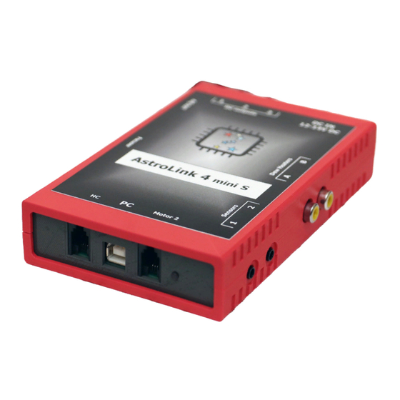
Page 8: Connecting Device
AstroLink 4 mini MaxIm, or any other ASCOM compliant software. Also scripting support is available for automation of acquisition process. Created with the Personal Edition of HelpNDoc: Create iPhone web-based documentation Connecting device It is general rule of thumb to make all cable connections before turning on power. This also applies to AstroLink device. -
Page 9: Basic Operations
AstroLink 4 mini Created with the Personal Edition of HelpNDoc: News and information about help authoring tools and software Basic operations AstroLink 4.0 device can be controlled from computer in two modes: · Direct control. Then AstroLink 4.0 panel connects to device directly and no other software can control any AstroLink 4.0 functionality... -
Page 10: 3Rd Party Software
AstroLink 4 mini To connect AstroLink 4.0 panel software to the device for the first time follow these steps: · make sure all cables are connected · turn on power supply. After a few seconds you should hear a double beep ·... -
Page 11: Revision 2
AstroLink 4 mini Created with the Personal Edition of HelpNDoc: Full-featured Kindle eBooks generator Revision 2 Here is the board in revision 2. Changes list: · regulated voltage module is now oriented correctly, so you can adjust voltage without unscrewing the board ·... -
Page 12: Connecting Peripherals
AstroLink 4 mini Created with the Personal Edition of HelpNDoc: Free EBook and documentation generator Connecting peripherals In the following sections details on connecting peripherals to AstroLink device are described. Created with the Personal Edition of HelpNDoc: Create cross-platform Qt Help files Stepper focuser motor AstroLink device can power both unipolar and bipolar stepper motors. -
Page 13: Dc Focuser Motor
AstroLink 4 mini Created with the Personal Edition of HelpNDoc: Free Kindle producer DC focuser motor DC focuser motor output is compatible with SW Motofocuser. DC motor that you want to connect to RJ9 4pin socket can drain maximum 1.2A current. RJ9 socket connection:... -
Page 14: Sensors
AstroLink 4 mini Created with the Personal Edition of HelpNDoc: Easily create PDF Help documents Sensors Two sensors may be connected to the AstroLink 4.0 mini device. One DHT22 temperature/humidity sensor can be connected to port Sensor 1. To the port Sensor 2 DS1820 temperature sensor can be connected. -
Page 15: Power Outputs
AstroLink 4 mini Sensor DHT22 DS1820 Jack plug pin Vcc (+5V) L (tip) Data R (middle) C (common) Created with the Personal Edition of HelpNDoc: Easily create iPhone documentation Power outputs There are three switched DC power outputs in the AstroLink mini device. Each of DC power output can provide up to 5A (however total current drawn from AstroLink mini device cannot exceed 10A). -
Page 16: Regulated Voltage Output
AstroLink 4 mini Voltage at PWM output is switched from zero to the voltage that AstroLink mini device is supplied (so it can be in a range 11-14V). There is no additional voltage regulator for PWM outputs. If you need to switch more than 3A you can use Power switch additional module. -
Page 17: Manual Control
AstroLink 4 mini Created with the Personal Edition of HelpNDoc: iPhone web sites made easy Manual control There is five button remote controller available (sold separately) for AstroLink 4.0 mini device. Controller needs to be connected to the proper input socket (labeled as Control), and manual control option needs to be enabled in AstroLink 4 panel software. -
Page 18: Controlling Components
Generate Kindle eBooks with ease Controlling components AstroLink 4 mini device functions can be controlled using dedicated software - AstroLink 4 mini panel. When opened for the first time and connected to the device panel may look like this: Panel is divided into several sections that are responsible for specific functions control. In the next chapters each section will be described in details starting from the connection to the device. -
Page 19: Focuser Control
AstroLink 4 mini checked each time the connection to the device is established AstroLink will reset, so its state will be restored to the power on state. It can be useful in case when AstroLink is not responding and you work remotely and cannot switch it off and on. - Page 20 AstroLink 4 mini 1. these fields are read only. First field presents current focuser position in steps, second presents focuser tube position in mm 2. these buttons can be used to relative movement of the focuser. Once '+' or '-' button is pressed focuser will be moved with the selected number of steps in the desired direction.
- Page 21 AstroLink 4 mini · Hold motor on idle - when this is checked stepper motor will be powered when stopped. It can then provide additional holding torque to your focuser, however more current will be drawn, and motor temperature will increase. When using microstepping module motor will always be powered when stopped.
-
Page 22: Dc Focuser Control
AstroLink 4 mini Created with the Personal Edition of HelpNDoc: Full-featured EPub generator DC focuser control DC focuser motor is controller by sending two parameters: move time in milliseconds and PWM duty cycle in %. Move time is the time the DC motor will rotate. PWM duty cycle parameter is responsible for torque of the DC motor. -
Page 23: Power Outputs Control
AstroLink 4 mini Created with the Personal Edition of HelpNDoc: Produce electronic books easily Power outputs control There are two sections related to power control in AstroLink 4.0 mini device. Power section is mainly informative - it contains following fields: ·... - Page 24 AstroLink 4 mini · also buzz with device buzzer - when one or more alerts is triggered there will be sound signal emitted from the AstroLink device · also alert with system sound - when one or more alerts is triggered there will be system sound alert played in the computer When any of alert values is close to defined limit corresponding field becomes orange.
-
Page 25: Sensors And Pwm Outputs Control
AstroLink 4 mini There are also four buttons at each setting windows bottom: Defaults will cause all fields to be populated with default values. Close will close settings window without saving values to the device. Save will store settings into the AstroLink device EEPROM memory. They will be preserved when power is down. - Page 26 AstroLink 4 mini There is settings window available after clicking on cogwheel button. In this window you can change sensor labels, so it can have some meaning, like 'OTA temp.' or 'Mirror dew-point'. An in the second tab called Temp. change alerts you can set temperature change monitor parameters: ·...
- Page 27 AstroLink 4 mini Another section is PWM. In this section each of two PWM outputs has corresponding field where current PWM output value can be read. Additionally there is select-box, where you can set required PWM value for each output. Value can be set from 0 to 100% and there are two additional operation modes: ·...
-
Page 28: Other Functions
AstroLink 4 mini Third tab AUTO contains parameters used when AUTO mode is selected for PWM output: · Temperature sensor - selected sensor will be used to measure temperature for PWM control · Temperature preset [C] - PWM output power will be adjusted to keep selected sensor at the given temperature ·... -
Page 29: 3Rd Party Software
AstroLink 4 mini 2. This check-box controls buzzer - if you uncheck this field, buzzer will not beep 3. After clicking at the logo icon small information window will popup - it contains firmware version information 4. Status bar displays several different informations, that are visible depending on context. It is read only field 5. - Page 30 AstroLink 4 mini Additional useful option is to run your own scripts, where you can control all AstroLink functions. 30 / 49...
-
Page 31: Additional Modules
AstroLink 4 mini Created with the Personal Edition of HelpNDoc: Easily create Qt Help files Additional modules Created with the Personal Edition of HelpNDoc: Create HTML Help, DOC, PDF and print manuals from 1 single source Microstepping module Microstepping module is a small box that can be used to control bipolar stepper motors with high accuracy (up to 1/32 step). -
Page 32: Hand Controller Module
AstroLink 4 mini Make all connections before switching power on. Created with the Personal Edition of HelpNDoc: Free CHM Help documentation generator Hand controller module Hand controller module is simple five buttons keyboard that allows to perform basic operations. Hand controller needs to be connected to device before power is turned on. -
Page 33: Sky Temperature Sensor
AstroLink 4 mini Created with the Personal Edition of HelpNDoc: Free CHM Help documentation generator Sky temperature sensor Sky temperature sensor is additional module available for AstroLink 4 device. It contains remote temperature sensor (pyrometer) that can sense sky temperature. Basing on this information cloud coverage can be determined. - Page 34 AstroLink 4 mini · temperature, humidity and dewpoint measured by DHT22 sensor (if connected) · temperature measured by DS1820 sensor (if connected) · sky temperature and difference between sky and ambient temperature (if sky temperature sensor is connected) · focuser position in steps ·...
- Page 35 AstroLink 4 mini files. · Data collection sampling rate - you may choose here how often data should be collected. Actual data is always sampled two times per second. This setting determines how many samples are averaged to create data point in the chart. Recommended values are 5 or 10 seconds, unless you need to have it collected more often.
-
Page 36: Overcurrent And Overvoltage Protection
AstroLink 4 mini Created with the Personal Edition of HelpNDoc: Generate Kindle eBooks with ease Overcurrent and overvoltage protection AstroLink panel contains settings to provide overcurrent and overvoltage protection. Both input voltage and total output current is monitored 200 times per second and measured values are compared to user settings. -
Page 37: Temperature Compensation
Free HTML Help documentation generator Temperature compensation Temperature compensation in AstroLink 4 mini is implemented in a linear way. So there is only one parameter that describes how temperature affects the focus point. It is not perfect approach, however its accuracy is good enough to most amateur setups. -
Page 38: Compensation Calculator
AstroLink 4 mini Created with the Personal Edition of HelpNDoc: Free iPhone documentation generator Compensation calculator Compensation calculator is simple tool that can be used to calculate compensation coefficient basing on temperature and focuser position points read from AstroLink panel. Compensation calculator can be found in the menu as shown below: There is two column table on the left part and data points plot. - Page 39 AstroLink 4 mini If the collected data points make a shape of a curve that crosses calculated compensation line, it indicates that your setup focus point does not change in linear way in the temperature range you choose. But you may still use compensation with different value for different temperature ranges.
- Page 40 AstroLink 4 mini You need to enter data points collected with one filter only! There can be focus shift between different filters, and calculated coefficient may not be accurate. 40 / 49...
-
Page 41: Scripting Support
Easily create iPhone documentation Scripting support You can also control AstroLink 4 mini device using scripts to automate acquisition process. All ASCOM interfaces (AstroLink 4m Focuser, AstroLink 4m DC focuser, AstroLink 4m Switch, AstroLink 4m Observing Conditions) are available and can be controlled from the script. You can find simple script example in the Temperature compensation section. - Page 42 AstroLink 4 mini · sensor 2 temperature · sensor 2 humidity · sensor 2 dew point · PWM out 1 value · PWM out 2 value · DC out 1 value · DC out 2 value · DC out 3 value ·...
-
Page 43: Regulated Voltage Application
Regulated voltage application Regulated voltage output in AstroLink 4 mini device is built on DC to DC converter. It can provide 1.5A maximum continuous current, and 2.5A peak current (for less than 3s). Output voltage can be set in the range from 3 to 10 volts. -
Page 44: Troubleshooting
AstroLink 4 mini Created with the Personal Edition of HelpNDoc: Create cross-platform Qt Help files Troubleshooting AstroLink log files All AstroLink log files are created in the My Documents/AstroLink folder. Files that name contains only current date are data collections from... - Page 45 AstroLink 4 mini outputs control section for details Stepper motor does not rotate after clicking plus or minus button and one beep is heard · next move position exceeds limits (is either below zero or over Maximum position setting). See...
-
Page 46: Ground Loops
AstroLink 4 mini Created with the Personal Edition of HelpNDoc: Easily create EBooks Ground loops Ground loop in electrical system occurs, when two points that should have the same potential actually have different voltages. Ground loop in astroimaging setup may occur, when ground (i.e. minus of power supply voltage) is connected to one receiver with more than one cable path. -
Page 47: How To Check Versions
AstroLink 4 mini Created with the Personal Edition of HelpNDoc: iPhone web sites made easy How to check versions If you want to check current version of software, firmware and device revision you need to connect to the device and then click on the logo image next to Connect button. Then small window will be displayed with... - Page 48 AstroLink 4 mini Created with the Personal Edition of HelpNDoc: iPhone web sites made easy Software update New software version can be found at http://astrojolo.com/astrolink-4-0-mini/ page. There are two independent software components - AstroLink Local Server and AstroLink Panel. To update your software you need to: ·...
- Page 49 AstroLink 4 mini Created with the Personal Edition of HelpNDoc: Easily create Web Help sites Firmware update Up to date firmware can be checked and downloaded from page http://astrojolo.com/astrolink-4-0-mini/ . To upload new firmware to AstroLink device you need also to download XLoader software. Then you need to perform following steps: 1.
Need help?
Do you have a question about the AstroLink 4 mini and is the answer not in the manual?
Questions and answers