
Related Manuals for BUFFALO TURBINE BT-MEGA


Summary of Contents for BUFFALO TURBINE BT-MEGA
- Page 1 BUFFALO TURBINE 180 Zoar Valley Road Springville, NY 14141 TEL: 716 592 2700 FAX: 716 592 2460 EMAIL: info@buffaloturbine.com WEBSITE: www.buffaloturbine.com BUFFALO TURBINE'S BT-MEGA ORIGINAL INSTRUCTIONS AND PARTS MANUAL 12/19-BT MAN...
-
Page 2: Table Of Contents
Exploded Parts Diagram (Before Serial # 28115) Exploded Parts Diagram (Serial #28115-29333) Exploded Parts Diagram (After Serial # 29333) BT-MEGA Parts Sub-Assemblies Bill of Materials for BT-MEGA 19-20 BT-MEGA Wireless Remote System Manual Wiring Schematic for Wireless Remote System Wireless system warranty information... -
Page 3: Introduction
This Manual covers the BT-MEGA Turbine Blower. Keep this manual handy for frequent reference and to pass on to new operators or owners. Call your Buffalo Turbine dealer or distributor if you need assistance, information, or additional copies of the manuals. -
Page 4: Safety
YOU are responsible for the SAFE operation and maintenance of your Buffalo Turbine Debris Blower. YOU must ensure that you and anyone else, who is going to operate, maintain or work around the Buffalo Turbine Blower be familiar with the operating and maintenance procedures and related SAFETY information contained in this manual. -
Page 5: Safety Decals
SAFETY DECALS The types of decals on the blower unit are shown below. Good safety requires that you familiarize yourself with the various Safety Decals, the type of warning and the area, or particular function related to that area that requires your SAFETY AWARENESS.* THINK SAFETY! WORK SAFELY! !ATTENTION! KEEP HANDS, FEET AND CLOTHING AWAY FROM POWER DRIVEN PARTS. -
Page 6: Transport Safety
Cover with a weatherproof tarpaulin and tie down securely. SIGN-OFF FORM Buffalo Turbine recommends that anyone who will be operating and/or maintaining the Buffalo Turbine Blower must read and clearly understand ALL Safety, Operating and Maintenance information presented in this manual. ... -
Page 7: Warranty Information
Obligation under this warranty shall extend for a period of 10 years from date of purchase and, at the option of Buffalo Turbine, replacement of any parts found, upon inspection by Buffalo Turbine, to be defective. -
Page 8: 3.1 Warranty Registration Form
WARRANTY REGISTRATION FORM & INSPECTION REPORT Any units not registered with Buffalo Turbine are not eligible for warranty claims This form must be filled out by the dealer and signed by both the dealer and the customer at the time of delivery Dealer’s Name... -
Page 9: Operations
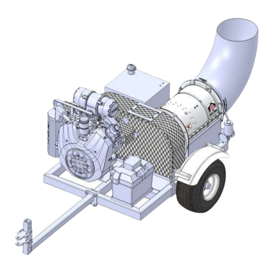
TO THE NEW OPERATOR OR OWNER Buffalo Turbine Debris Blowers are designed to quickly and efficiently, blow away leaves, cuttings and other debris. The material is conveyed on a stream of high volume and velocity of air to remove it from the area of concern. When the material is removed, it gives a neat, professional look to the working area. -
Page 10: Model Bt-Mega Assembly Instructions
MODEL BT-MEGA Assembly Instructions Fill engine oil to proper level. (overseas shipments) Fill each cell to proper level (Dry Cell Battery) with battery-grade sulfuric acid of 1.265 specific gravity. Battery and acid must be at a temperature of 60F to 100F (16C to 38C) at the time of filling (overseas shipments). -
Page 11: Field Operation
Do not allow children to play around the stored unit. TROUBLE SHOOTING The Buffalo Turbine Debris Blower uses a high volume and velocity of air to move material from one place to another. The system is simple and reliable requiring minimal maintenance. -
Page 12: Machine Specification
Machine Specifications Model BT-MEGA Series Length: 112” With nozzle 92” Without nozzle 70” With nozzle installed but Without trailer arm 50” Without nozzle and trailer arm installed Width: 56” With fender/axle mount and tires 36.5” Without fender/axle mount and tires 45”... -
Page 13: Maintenance
MAINTENANCE SECTION Maintenance Safety Set Blower on a level surface, stop engine, set park brake, remove ignition key and wait for all moving parts to stop before dismounting to service, adjust or repair. Reinstall and secure all guards removed for servicing before starting to use machine again. *We recommend wearing gloves when removing or installing the guard to avoid getting cut* Securely support machine with blocks or safety stands when changing tires or working beneath it. -
Page 14: Belt Maintenance
Belt Maintenance After using the Blower unit for a long period of time, the belt will stretch and wear and need replacing. REPLACING THE BELT USE THE ILLUSTRATION FROM BELOW FOR REFERENCE To change the belt follow this procedure: Remove the guard around belts and pulleys. (Figure 1) Loosen pushover bolt and nut (Figure 2) Remove belt. -
Page 15: Service Checklist
SERVICE CHECKLIST See Lubrication and Maintenance sections for details of service. Copy this page to continue record. TURN OFF ENGINE, REMOVE KEY & DISCONNECT BATTERY BEFORE SERVICING BLOWER UNIT CODE: LUBRICATE-(L) / CHECK-(*) / CHANGE-(C) / REPLACE-(B) / CLEAN-(CL) SCHEDULED MAINTENANCE HOURS ________________________ SERVICED BY ____________________ MAINTENANCE 8 hrs or daily... -
Page 16: Exploded Parts Diagram (Before Serial # 28115)
Before Serial # 28115... -
Page 20: Bill Of Materials For Bt-Mega
BILL OF MATERIALS FOR BT-MEGACE REF PAGE # DESCRIPTION 1100 3/8-24 X 1-1/4 HHCS ZINC GR 5 1101 3/8-24 X 1-1/2 HHCS ZINC GRADE 5 1102 3/8-24 X 1-3/4” HHCS 1105 3/8-24 HEX NUT ZINC PLATED GRADE 5 1107 3/8 LOCK WASHER ZINC PLATED 1108 3/8 FLAT WASHER ZINC PLATED 1110... - Page 21 BILL OF MATERIALS FOR BT-MEGACE (continued) REF PAGE # DESCRIPTION 2597 CH1000-3022 KOHLER ENGINE 2634 ACTUATOR PIN, 40HP ENGINE 2639 RUBBER GROMMET, 5/8” BORE 2851 AEROSPACE POLYMER NOZZLE 3007 CONSTANT TENSION HOSE CLAMP 3090 ACTUATOR BRACKET, 40HP ENGINE 3098 MEGA BLOWER ASSEMBLY 3113 FRAME, MEGA 3147...
-
Page 22: Bt-Mega Wireless Remote System Manual
If a valid code from an already registered TX is received, the receiver will go directly into normal operating mode. This is to speed up the startup time. NOTE: Breaking any warranty seal will void the equipment’s warranty, consult with Buffalo Turbine at 716-592-2700 before proceeding. -
Page 23: Wiring Schematic For Wireless Remote System
Receiver (Part # 3573) Wire color Function Terminal number Yellow +12VDC Black -0VDC, Ground Gray Nozzle 1 White Nozzle 1 Purple Throttle Relay Green Throttle Relay Future models will have all black wires sequentially numbered 1-12 and matching terminal numbers above. -
Page 24: Wireless System Warranty Information
Repairs and maintenance must be authorized by Buffalo Turbine. Use spare parts from Buffalo Turbine only. Contact Buffalo Turbine at 716-592-2700 if you require service or other assistance. Keep the product in a dry, clean place. Keep contacts and antennas clean. Wipe off dust using a slightly damp, clean cloth. Never use... -
Page 25: Wireless Remote System Diagnostic Tests
Troubleshooting For MEGA Remote / Receiver Symptom – Does not throttle up properly. 1. Disconnect grey plug connected to the receiver. Grey plug must be removed by compressing the side tabs and pulling straight out as shown in Ref #1. Check to ensure that each wire is securely attached to the grey connector plug (see Ref #2). - Page 26 Step 4. If proper voltage has not been verified contact Buffalo Turbine for further instructions. 4. The engine should be off for the following tests. Apply power to the throttle actuator directly.
- Page 27 Troubleshooting For MEGA Remote / Receiver Kit Symptom: Nozzle will not rotate properly 1. Disconnect grey plug connected to the receiver. Grey plug must be removed by compressing the side tabs and pulling straight out as shown in Ref #1. Check to ensure that each wire is securely attached to the grey connector plug (see Ref #2).
- Page 28 If rotation motor rotates in both directions, the motor is ok. If rotation motor will not rotate in either direction with power applied contact Buffalo Turbine. If rotation motor rotates in one direction but the other, contact Buffalo Turbine.
Need help?
Do you have a question about the BT-MEGA and is the answer not in the manual?
Questions and answers