Table of Contents
Advertisement
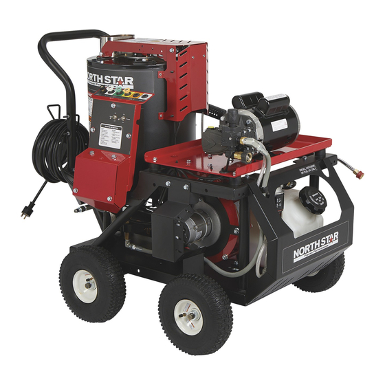
Electric Hot Water/Steam Pressure Washer
Instructions for Set-up, Operation, Maintenance & Storage
This pressure washer produces both cold and hot water high-pressure spray as well as wet steam. Cleaning
chemicals may be incorporated into the spray if desired. The pressure pump for this equipment is powered
by an electric motor and the water is heated by a diesel, kerosene/fuel-oil fired, down draft burner.
WARNING: SPECIAL HAZARDS
• Skin/Eye Injury: High-pressure spray can cause serious skin or eye injury, including injection injury if fluid pierces the skin.
Injection injury can result in blood poisoning and/or severe tissue damage.
• Burns: Hot spray can scald and burn skin. Hot surfaces of wand and burner, as well as hot exhaust from the burner can
cause burns.
• Slips/Falls: Spray discharge can cause puddles and slippery surfaces. Spray-gun kickback can cause operator loss of
balance and falls.
• Flying Debris: High-pressure spray can cause surface damage and flying debris.
• Fire/Explosion: Burner sparking can ignite fuel or other flammable liquids or vapors in the vicinity. Hot exhaust from burner
can ignite combustible materials.
• Chemical Exposure: Cleaning chemical vapors or contact with skin may be hazardous.
• Electric shock: Spray contact with electrical sources can cause electric shock.
• Electrocution: Improper connection of the equipment or grounding conductor can result in a risk of electrocution.
• CO Poisoning: Exhaust from burner contains carbon monoxide, a poisonous gas that can cause carbon monoxide poisoning
and possible death if inhaled.
Inspect Upon Delivery: STOP! Closely inspect to make sure no components are missing or damaged. For missing
or damaged components please contact Product Support at 1-800-270-0810.
Check Pump Oil: Pump is shipped with oil. Check pump oil level before starting.
-
Remove shipping tape and black vent plug (if present) from pump oil fill cap (CAT Pumps)
-
Pump is supplied with Vented fill cap (General Pumps only)
Water Flow Requirements: Make sure your supply water flow rate is 20% higher than the pressure washer's flow
rate (See Specification Section for unit specific flow rates), and that your water is clean and particle free.
Chemical Spraying: Use only NorthStar brand or equivalent washer chemicals designed for pressure washer use.
Maintenance Schedule: Pump, burner fuel filter, burner coil and electrodes require periodic checking and servicing
to keep pressure washer functioning efficiently. See "Maintenance & Repair" for frequency of servicing.
Any Questions, Comments, Problems or Parts Orders
Owner's Manual
Portable Outdoor – Use Only
Equipment Protection Quick Facts
Call NorthStar Product Support 1-800-270-0810
M1574210B
ITEM NUMBER: 1574210, 1574211,
SERIAL NUMBER: _____________
1
1574212, 1574213
Advertisement
Table of Contents

Related Manuals for North Star 1574210


Summary of Contents for North Star 1574210
-
Page 1: Equipment Protection Quick Facts
M1574210B ITEM NUMBER: 1574210, 1574211, 1574212, 1574213 SERIAL NUMBER: _____________ Owner’s Manual Electric Hot Water/Steam Pressure Washer Instructions for Set-up, Operation, Maintenance & Storage Portable Outdoor – Use Only This pressure washer produces both cold and hot water high-pressure spray as well as wet steam. Cleaning chemicals may be incorporated into the spray if desired. -
Page 2: Table Of Contents
Table of Contents Equipment Protection Quick Facts ................................1 TABLE OF CONTENTS ................................. 2 ABOUT YOUR PRESSURE WASHER ............................4 SPECIFICATIONS ..................................5 COMPONENT IDENTIFICATION ..............................6 SPECIAL EQUIPMENT SAFETY FEATURES ..........................8 High Pressure Safety Device (Rupture Disc) ............................. 8 Temperature Sensor .................................... - Page 3 PUMP EXPLODED-GP EVO-O ..............................45 PUMP EXPLOSION-CAT 4DX ..............................48 PUMP EXPLOSION-GP EP1812 PUMP ............................52 WIRING DIAGRAM - 1574210 ..............................54 WIRING DIAGRAM - 1574211 ..............................55 WIRING DIAGRAM – 1574212 & 13 ............................56 SUMMARY OF IMPORTANT SAFETY INFORMATION ......................57 LIMITED WARRANTY .................................
-
Page 4: About Your Pressure Washer
About Your Pressure Washer Thank you for purchasing a NorthStar hot water Site Selection. Pressure washers used while the open pressure washer! It is designed for long life, flame burner is used to heat the water are for dependability, and top performance. OUTDOOR USE ONLY unless specific exhausting guidelines are met. -
Page 5: Specifications
Specifications MODEL Model # 1574210 1574211 1574212 1574213 FLOW OUTPUT Pressure Rating 1700 psi 2000 psi 2750 psi 2000 psi Flow Rate 1.5 gpm 1.5 gpm 2.5 gpm 4.0 gpm Minimum Water Supply 1.8 gpm 1.8 gpm 3.0 gpm 4.8 gpm... -
Page 6: Component Identification
Component Identification SEE DETAIL A SEE DETAIL C DETAIL B DETAIL C SEE DETAIL B DETAIL A DETAIL D BURNER FUEL PUMP BLOWER ASSEMBLY SEE DETAIL D Fig.1574210_1 SCALE 1.200 Ref # Description Ref # Description Ref # Description High PSI limit switch High Pressure Outlet Heat Switch Flow Switch... - Page 7 Component identification High, PSI limit switch: This is a backup safety 13. GFCI Cord: Device provides additional protection feature, if the system pressure exceeds the set form the risk of electric shock. pressure this device will stop the burner from firing. 14.
-
Page 8: Special Equipment Safety Features
Special Equipment Safety Features This unit is equipped with the following safety features: pump from overheating. The thermal relief valve is located on the pump manifold’s low-pressure port. High Pressure Safety Device (Rupture Disc) Spray Gun Safety Latch Acts as a backup safety feature. If the Pressure Control Has a built-in trigger safety latch to guard against Valve (Unloader) malfunctions, this separate high- pressure safety device will open and relieve excess... -
Page 9: Safety
Safety Hazard Signal Word Definitions This is the safety alert symbol. It is used to alert you to potential personal injury hazards. Obey all safety messages that follow this symbol to avoid possible injury or death. DANGER (red) indicates a hazardous situation, which if DANGER not avoided, will result in death or serious injury. -
Page 10: Safety Decal Locations
Safety Decal Locations Fig.1574210_2 Fig.1574210_2 Always make sure safety labels are in place and in good condition. If a safety label is missing or not legible, order new labels or unsafe operation could result. To order replacement safety labels, call NorthStar Product Support at 1-800-270-0810. -
Page 11: Assembly And Initial Set-Up
Assembly and Initial Set-Up Step 1. Inspect & Unpack Step 2. Assembly Inspect the pressure washer immediately after you You must assemble your pressure washer before it can receive delivery for missing parts or damage. Find and be used. Refer to Fig.1574210_5 and follow the steps separate components identified in Fig.1574210_3 and listed below: Figure 1574210_4. -
Page 12: Step 4. Verify Electrical Connection
Assembly and Initial Set-Up Extension Cord Cat 4DX AND 4DNX Pump GP EVO Pump (For 1574210) (For 1574211 & 12) fill cap This appliance cord is equipped with a GFCI, do not use fill cap extension cords. If the appliance cord is not equipped with a GFCI, the appliance and any extension cord used should be connected only to a GFCl-protected power source. -
Page 13: Step 5. Moving And Handling
Assembly and Initial Set-up Step 5. Moving and Handling WARNING: Lifting hazard The pressure washer is heavy. It can crush and cause serious injury if it rolls out of control or tips over. Follow the instructions below for safely moving the pressure washer. -
Page 14: Before Each Use
Burner Fuel System (if heated water to be used) Pump Model Oil Type Inspect Burner fuel system for leaks BEFORE starting GP EVO 1574210 SAE 30 Non-Detergent Oil or pressure washer. Look for: Pressure Washer Pump Oil 1574213 EP1812 (Part# 4043) Signs of leaks, wetted areas, or deterioration •... -
Page 15: Filling Burner Fuel Tank (If Heated Water To Be Used)
Before Each Use Filling Burner Fuel Tank (if heated water to Away from all building windows and air intakes • be used) (when burner used). Away from other heat-generating equipment. • WARNING: Flammability hazard Positioning: Burner fuels are highly flammable. Turn the machine off and allow it to cool for at least 2 minutes before The pressure washer should be positioned on a •... - Page 16 Before Each Use An abundant amount of air must be available for • proper combustion and cooling. Do not install in small, enclosed areas without an ample circulation of supply air. For more details, refer to NFPA 31: Standard for •...
-
Page 17: Operation
Operation Step 1. Connect Hoses, Water Supply, and WARNING: Incompatable component Spray Nozzle hazard NEVER operate this pump with components (such as Note: The electrical power and pump are both off hose, connections, and spray gun) rated for lower during Step 1 procedures. pressure and/or temperature limits than the machine’s Attach Garden Hose to Water Supply maximum rated pressure and temperature, or... -
Page 18: Attach Nozzle To Spray Gun
Operation Note: Use only the black low-pressure nozzle for spraying chemicals, which provides the proper mixing ratio. Attach Nozzle to Spray Gun Correct Not Fully WARNING: Depressurize first Insertion Inserted Any time you remove/install/change a nozzle, you Figure 10b must depressurize hose line by squeezing the Collar Collar NOT spray gun trigger while the Motor is off. -
Page 19: Personal Protective Gear
• Make sure you have attached the appropriate spray nozzle. • Clear the cleaning area of all persons. Keep children and pets away. FOR 1574210 FOR 1574211, 12 Starting UNLOADER • Plug unit into a grounded outlet. Press RESET on the GFCI (if applicable). - Page 20 Always dispose of hazardous fluids per local, • follow instructions for spraying. state, and national guidelines. FOR 1574211 & 12 CAUTION: Chemical mixture FOR 1574210 The special NorthStar braided chemical hose when PUMP PUMP placed within a liquid and attached at the pump’s PUMP...
-
Page 21: Hot Spray Procedure
Operation Hot Spray Procedure For Model 1574210 For Model 1574211, CAUTION: Metal burn hazard 12 and 13 Use of burner will make spray gun hot. Avoid touching wand. Serious burns from hot metal could occur if 1.Turn heat switch to 1.Turn thermostat... -
Page 22: Storage
Storage Between-Use Storage Before storing, let machine cool for at least 5 minutes, as a hot engine can be a fire hazard. Place in a secure RV Antifreeze location where it will not be started by untrained Supply Bucket persons. Hose An appropriate storage location is: Clean and dry. - Page 23 Storage Alternately the system can be blown out with compressed air: Note: although this method can be effective for winterizing, the above antifreeze method is preferred because it ensures the entire plumbing system is flushed and lubricated. Materials: 1. Properly rated fittings (80 psi or higher) to connect air supply to inlet connection (¾”...
-
Page 24: Maintenance & Repair
Maintenance & Repair WARNING: Maintenance hazards ALWAYS shut off water supply, bleed water pressure, turn off motor and unplug electrical cord before cleaning, adjusting, or servicing the pressure washer. After servicing, make sure all guards and cover shields are replaced before using. Follow all safety rules and recommended maintenance instructions. -
Page 25: Clean Inlet Filter For Garden Hose
Maintenance & Repair section of this manual to determine the type of pump that came equipped with this pressure washer) a. For GP pumps: Use SAE30 non-detergent oil or Pressure Pump Oil Item #4043 Good b. For Cat pumps: Use SAE30 non-detergent oil or Cat Pump Oil Item #22158. - Page 26 Maintenance & Repair Choose a well-ventilated area and use the recommended 2. Add commercial coil cleaner to water and mix. Use PPE (personal protective equipment) of the coil cleaning an acid resistant 5-gallon bucket. chemical manufacture when descaling the coil and/or using 3.
-
Page 27: Inspect And Clean The Flow Switch As Needed
Maintenance & Repair Inspect and clean the flow switch as needed Mineral build-up and/or debris within the flow switch can occur and may affect burner operation if not periodically cleaned. Mineral build-up and/or debris can stop the movement of the shuttle inside the flow switch body. Shuttle Shuttle movement is important because the burner will Assembly... -
Page 28: Inspect Heating Coil And Desoot As Needed
Maintenance & Repair Cap Fitting; TORX Torque to 100lb-in Screw Enclosures 10) On the elbow on the inlet of the coil, remove any remaining thread tape/sealant. Re-apply new thread tape/sealant on the elbow. Re- Body connect the swivel to the elbow. Hand-tighten the swivel onto the elbow, and once snug, using a wrench continue to tighten the swivel two 6) Rinse “Body”... -
Page 29: Inspect/Clean/Adjust Electrodes
2-man job each with the ability to lift Label dimension ITEM# at least 65 lbs. 10) Clean the coil. 1574210 11) Reassemble the coil and lids to the machine. 1574211 .188 .188 .109 Make sure the white insulation remains in place. -
Page 30: Perform Engine Maintenance
Maintenance & Repair Instructions for inspecting: 1) Remove flame sensor bracket Flame sensor bracket Fig157115-4 2) Following normal starting procedure with burner and thermostat off. With unit running look through flame sensor sight glass to observe if there is a spark. Perform Engine Maintenance All mechanical equipment, no matter how well designed, will need maintenance and repairs. -
Page 31: Oil Burner Adjustment (Only Needed If White Exhaust Smoke Appears)
10 is fully open and for is opened to wide and will need further units 1574210, 11 & 1574212 0 is fully closed adjustment. and 9 is fully open). -
Page 32: Troubleshooting
Troubleshooting Pressure Washer Will Not Run At All - No Power Causes Solutions Machine turned OFF Turn Pump switch ON Line circuit breaker tripped Check for tripped circuit breaker in building Circuit Breaker Trips Causes Solutions Voltage too low Check the voltage Circuit Breaker Overloaded Make sure there is no other equipment using the same circuit. - Page 33 Troubleshooting Pressure Washer Runs but Surges or Cycles While In Bypass Causes Solutions Leak between unloader and gun. Check all connections between unloader and gun for leaks. Tighten loose components and replace damaged components. Gun leaking internally Replace spray gun Rupture Disc Sprays Water Causes Solutions...
-
Page 34: Major Components
Major Components Fig.1574210_14 MAJOR COMPONENTS Ref.# Description Page# Frame Heat Exchanger Blower and Fuel Pump Motor, water pump and fuel system Accessories- Gun, hose, chemical injector These components go into more detail on the following pages. -
Page 35: Parts Explosion: Frame
Parts Explosion: Frame Fig.1574210_15... - Page 36 1574210, 11 803127 STRAIN RELIEF, 3/4" 2 HOLE (.34-.177") - PW 1574212, 13 803127 STRAIN RELIEF, 3/4" 2 HOLE (.34-.177") - PW 1574210 803142 DECAL, CONTROL BOX, 1574210 - HWEPW 1574211, 12, 13 803143 DECAL, CONTROL BOX, 1574211-13 - HWEPW...
- Page 37 WELDMENT, CONTROL BOX BACK COVER - PW 82651 RIV-NUT 5/16-18 GR .031-.157 802974 PLATE, FUEL/PUMP/MOTOR COVER - PW 789635 GROMMET, 3/16 GW X 1 GD - AC 1574210, 11, 12 779666 CLAMP, 1" LOOP 1574213 1574210, 11 803126 CLAMP, LOOP 5/16...
- Page 38 Parts Explosion: Heat Exchanger 1.35 1.36 1.15 1.24 1.27 1.13 1.16 1.6.1 1.25 1.22 1.17 FOR 1574213 1.23 1.18 1.34 1.32 1.21 1.26 1.11 1.12 1.29 1.30 1.12 1.28 1.33 1.19 1.31 1.27 1.10 1.20 1.14 Fig.1574210_16...
-
Page 39: Parts List: Heat Exchanger
DESCRIPTION Model Heat exchanger assembly 82621 Bolt, 5/16-18 x 3/4" hex head flange 796266 Fuel line guard, top 1574210, 11, 12 797692 HX Fuel Line Guard, Top 1574213 798383 Decal, Flame Sensor Lens Cleaning Instructions 796496 Decal, Electrical Shock Hazard... - Page 40 Parts List: Heat Exchanger ITEM PART# DESCRIPTION Model 779847 Adapter, 8MP-8FP - PW 800102 Thermostat, Fixed 250° 1574210 793966 NTC Thermistor 10Kohm 1574211, 12, 13 799855 Fitting, coil inlet manifold 17141 Clamp, 3/4” Hose 797121 Switch, flow 12.0 GPM 5000PSI-PW 800127 Hose, 3/4"...
- Page 41 HHCS, GR5Z 3/8-16 X 3 1/4 1574210, 13 82109 HHCS, GR5Z 3/8-16 X 3 1/4 1574211, 12 802061 DAMPER, MED CAP - PW 1574210, 11, 12 801874 DAMPER, LARGE CAP - PW 1574213 801982 ASSEMBLY, AC HOUSING MED. INLET - PW 82613...
- Page 42 Parts Explosion: Motor, Water Pump & Fuel System PUMP EXPLODED VIEW FUEL SYSTEM 13.1 FOR 1574210 FOR ALL MODEL PUMP EXPLODED VIEW PUMP EXPLODED VIEW FOR 1574211 & 12 FOR 1574213 Fig.1574210_18...
- Page 43 FITTING, 3/8" NPT-M TO 3/4" FGH - PW 30484 1574211, 12 BYPASS,3/8 X 1/4, HEX BRASS(PW) 800783 1574213 FILTER, WASHER, 1/2" NPT X 3/4" FGH 35918 1574210, 11, 12 PROTECTOR, THERMAL,1/4 NPT-PW 777836 1574213 PROTECTOR, THERMAL 802097 SWITCH, FLOW 12GPM W/ PILOT 1574211...
-
Page 44: Parts Explosion: Accessories: - Gun, Hose, Chemical Injector
Parts Explosion: Accessories: - Gun, Hose, Chemical Injector ONLY FOR 1574213 Fig.1574210_19 ITEM PART# MODEL DESCRIPTION GUN WITH LANCE 779165 1574210, 11, 12 SPRAY GUN, ST-2605 - PW 1574213 777420 791274 1/4 QUICK COUPLER 796379 O-RING (NOT SHOWN) 1574210, 11, 12 791278 LANCE,18.5"... -
Page 45: Pump Exploded-Gp Evo-O
Pump Exploded-GP PUMP Ref# DESCRIPTION Ref# DESCRIPTION Not Available Crankcase GP90360000 O-ring, Ø 21.95x1.78 Not Available Crankshaft (EM12048EUITS) GP90258950 Seal Ring, Ø 12.0x18.5x4.5 GP 99179000 Screw, M6x06 GP90507080 Anti-extrusion Ring GP91822100 Ball Bearing GP90258900 Seal Ring, Ø 2.0x21.0x4.2 GP91846000 Roller Bushing GP83100051 Head Ring, Ø... - Page 46 Pump Exploded-GP PUMP Ref# DESCRIPTION Ref# DESCRIPTION GP90358700 O-ring Ø 1.11x1.78 GP98196800 Plug, G 1/8"x8 GP90358100 O-ring Ø 8.73x1.78 GP36355951 GP90357600 O-ring, Ø 6.75x1.78 GP99159400 Screw, M5x25 7984 GP36357100 Valve Seat GP36355451 Box Cover GP94739650 Spring, Ø 11.1x39.5 GP90360800 O-ring, Ø 28.30x1.78 GP36356970 Pressure Regulator GP99034400...
- Page 47 Pump Exploded-GP PUMP REPAIR KITS: KIT NO. GPK309 GPK400 GPK401 GPK402 INLET/OUTLET VALVE PLUNGER SEAL WITH KIT DESCRIPTION GASKET, CRANKCASE PLUNGER SEAL ASSEMBLY GASKET SUPPORT ITEM NO’S INCLUDED IN 39, 40 25, 26, 27, 28, 29 23, 24, 25, 26, 27, 28, 29 NUMBER OF PIECES...
-
Page 48: Pump Explosion-Cat 4Dx
Pump Explosion-CAT 4DX... - Page 49 Pump Explosion-CAT 4DX Ref# DESCRIPTION Ref# DESCRIPTION Not Available Screw CA941516 Inlet Fitting Assembly CA547153 Bearing Cover CA30516 Bolt Mount Assembly CA14041 O-Ring, Bearing Cover CA32088 Handle Adjustable (Not Shown) CA55337 Oil Seal CA46570 Adjusting Cap CA14488 Inner Ball Bearing CA45070 Lock Nut CA547048...
- Page 50 Pump Explosion-CAT 4DNX Ref# DESCRIPTION Ref# DESCRIPTION CA549360 Screw CA46233 Retainer, Seal CA547153 Bearing Cover CA49816 Seal CA14041 O-Ring, Bearing Cover Not Available Seal Case CA55337 Oil Seal CA13976 O-Ring For Seal Case CA14488 Inner Ball Bearing CA49824 Seal CA547048 Connecting Rod CA17428 O-Ring, Inlet...
- Page 51 Pump Explosion-CAT 4DNX Ref# DESCRIPTION Ref# DESCRIPTION CA547798 Adjusting Cap CA46254 Seat, Check Valve CA45070 Lock Nut CA13963 O-Ring, Check Valve Seat CA32094 Pressure Spring CA49765 Valve, Check CA549352 Spring Retainer CA45924 Spring CA45694 Piston Stem CA26133 O-Ring, Body CA20184 Back Up Ring O-Ring Kit Includes: 414, 415, 424, 428, CA31767...
-
Page 52: Pump Explosion-Gp Ep1812 Pump
Pump Explosion-GP EP1812 PUMP Ref# DESCRIPTION Ref# DESCRIPTION Not Available Manifold, Ø 18 GP98217600 Plug, 1/2” Bspx10 GP36202551 Valve Cage GP96751400 Gasket, Ø 21.5x27x1.5 GP94737600 Spring, Ø 9.4x14.8 GP96698000 Washer, Ø 7.5x15x0.5 GP36711501 Valve GP58210582 Gasket, Ø 3x94 GP36200366 Valve Seat Not Available Crankcase GP701115... - Page 53 Pump Explosion-GP EP1812 PUMP REPAIR KITS: Ø 18 KIT NO. GPK269 GPK270 GPK271 GPK274 Not Available 7 (2, 3, 4, 5, 6), 22, 23, 24, 25, 26, ITEM NO’S INCLUDED IN KIT 8, 9, 19, 20 22, 23, 24, 26, 28 18 (13, 14,15, 16, 17) 28, 29 NUMBER OF ASSY’S IN KIT...
-
Page 54: Wiring Diagram - 1574210
Wiring Diagram - 1574210 TSS SWITCH EVO-TSS WIRE CONTROL BOX WIRE NUT WIRE NUT FLOW SWITCH PUMP WIRE NUT MOTOR 2 POSITION LEVER LOCK WIRE NUT 2 POSITION POWER LEVER LOCK SWITCH BURNER SWITCH PLUG HI PRESSURE LIMIT CONTROL BOARD... -
Page 55: Wiring Diagram - 1574211
Wiring Diagram - 1574211 TSS SWITCH TSS-WIRE CONTROL BOX WIRE NUT THERMOSTAT WIRE NUT 2 POSITION BOARD LEVER LOCK FLOW SWITCH PUMP MOTOR WIRE NUT WIRE NUT POWER 2 POSITION SWITCH LEVER LOCK BURNER SWITCH PLUG HI PRESSURE LIMIT CONTROL BOARD CONTACTOR PLUG... -
Page 56: Wiring Diagram - 1574212 & 13
Wiring Diagram – 1574212 & 13 TSS SWITCH TSS-WIRE CONTROL BOX 2 POSITION LEVER LOCK WIRE NUT THERMOSTAT WIRE NUT BOARD FLOW SWITCH PUMP MOTOR POWER WIRE NUT SWITCH BURNER 2 POSITION LEVER LOCK SWITCH PLUG HI PRESSURE LIMIT CONTROL BOARD CONTACTOR PLUG... -
Page 57: Summary Of Important Safety Information
Summary of Important Safety Information This section provides a summary of the various safety procedures and measures that have been presented throughout the manual. Keep this summary handy and refer to it to refresh your memory about how to safely use your pressure washer. - Page 58 Summary of Important Safety Information • Adequate ventilation. The pressure washer needs adequate, unobstructed flow of air to allow for proper combustion and cooling. Situate so there is adequate clearance around pressure washer to allow for airflow – at least 7’ from any non-combustible wall or obstruction.
- Page 59 Summary of Important Safety Information • Position safely. Place sprayer on firm, level ground to prevent accidental falls and equipment tip-over. • Not in presence of combustibles. Do not use the pressure washer in the presence of flammable vapors, dust, gases, or other potentially combustible materials.
- Page 60 Summary of Important Safety Information • Keep spray away from electrical wiring. Spray contact with electrical wiring will likely result in severe electrical shock or electrocution. • Use only approved cleaning chemicals. Only chemicals specifically designed for use in pressure washers may be used. Never spray acids, corrosives, or abrasive or flammable liquids.
- Page 61 Summary of Important Safety Information SAFETY - INSPECTION/MAINTENANCE Inspect and maintain your pressure washer on a regular basis and repair as needed to keep it in safe working condition: • Turn off / relieve pressure first. Turn off pressure washer and relieve system pressure before inspection or maintenance before working on the Motor or pressure washer to prevent accidental starting.
-
Page 62: Limited Warranty
NorthStar Warranty Item # Consumer Warranty Period Commercial Warranty Period 1574210, 1574211, 2 years from date of purchase by user 2 years from date of purchase by user 1574212, 1574213 “Consumer use” means personal residential household use by a consumer. “Commercial use” means all other uses, including use for commercial, income producing or rental purposes or when purchased by a business. - Page 63 This page lift blank intentionally.
-
Page 64: California Proposition 65 Information
California Proposition 65 Information WARNING : This product can expose you to chemicals including acetaldehyde, which is known to the State of California to cause cancer, and carbon monoxide, which is known to the State of California to cause birth defects or other reproductive harm. For more information go to www.P65Warnings.ca.gov.
Need help?
Do you have a question about the 1574210 and is the answer not in the manual?
Questions and answers