
Related Manuals for EL-CELL ECD-3-nano


Summary of Contents for EL-CELL ECD-3-nano
- Page 1 User Manual Release 1.52 ECD-3-nano Electrochemical dilatometer © 2021 EL-Cell GmbH © 2017 EL-Cell GmbH...
- Page 2 EL-Cell GmbH maintains the right to make changes without further notice to products described in this manual to improve reliability, function, or design. EL-Cell GmbH does not assume any liability arising from the use or application of this product.
-
Page 3: Table Of Contents
User Manual ECD-3-nano Content 1 Product description ............................5 2 Features ................................8 3 Technical Data ..............................8 4 Safety Precautions ............................9 5 Unpacking................................ 9 6 Start-up and disassembly .......................... 12 7 Assembling the cell inside the glove box ..................... 18 8 Further assembly outside the glove box .................... - Page 4 User Manual ECD-3-nano Spring load (ECD-3), assy ........................42 REF electrode ECD, long, assy (1.4404) ..................43 19 Connector and Cable Pin-out ......................... 44 20 Technical support ............................46 21 Warranty ..............................46 Page 4 of 46 Release 1.52...
-
Page 5: Product Description
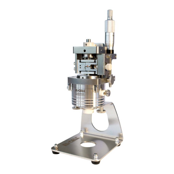
The ECD-3-nano electrochemical dilatometer is dedicated to the measurement of charge- induced strain (expansion and shrinkage) of electrodes down to the nanometer range. The ECD-3-nano has been particularly developed for the investigation of Li-ion battery and other insertion-type electrodes. It may, however, also be used for many other electrochemical systems utilizing aprotic organic electrolyte solutions. - Page 6 User Manual ECD-3-nano Basic structure of the ECD-3-nano: Sensor unit Details shown on the following page Cell body Bracket Page 6 of 46 Release 1.52...
- Page 7 User Manual ECD-3-nano Cut drawing of the ECD-3-nano: Sensor cable Capacitive sensor Micrometer screw Sensor plunger Excenter Flexure Locking screw Load Sensor Tip Spacer disc Glass T-Frit Shut-off valve Reference electrode Piston Page 7 of 46 Release 1.52...
-
Page 8: Features
2 Features The ECD-3-nano is an electrochemical dilatometer for measuring changes of thickness of the working electrode of a battery test cell. The main features of the ECD-3-nano are briefly described in the following: High resolution capacitive sensor system with <5 nm resolution, drift stability of <20 ... -
Page 9: Safety Precautions
Check the contents of the packages against the list given below to verify that you have received all of the required components. Contact EL-CELL, if anything is missing or damaged. NOTE: Damaged shipments must remain within the original packaging for freight company inspection. - Page 10 User Manual ECD-3-nano 9. USB stick containing EC-Link data logger software ECE1-00-0052-B 10. Allen wrench 2.5 mm WZG9059 11. Allen wrench 3 mm WZG9058 12. 3 x PE Seal II ECD-3 piston ECC1-01-0044-D 13. 3 x PTFE Seal ECD-3 piston ECC1-00-0044-C 14.
- Page 11 User Manual ECD-3-nano 23. Demonstration kit for ECD ECD1-00-0900-A 24. Allen wrench set (0.9 / 1.3 / 1.5 / 2) (4 pcs) ECC1-01-0028-A 25. Open end wrench AF7 ECC1-09-2037-A 26. Removing tool for ECD-3 piston ECC1-09-2005-A 27. Allen screw driver 2.5 mm WZG9003 28.
-
Page 12: Start-Up And Disassembly
User Manual ECD-3-nano 6 Start-up and disassembly Follow the same procedure beginning at step 3 when disassembling the instrument after an experiment has been completed. General advise: Practice the assembly procedure outside the glove box with dummy components before going for the real experiment. Make sure you have understood the how and why of each single step. - Page 13 User Manual ECD-3-nano 6.4 Screw off the cell body from the bracket. 6.5 Unscrew the spring load from the cell body. 6.6 Unscrew the reference electrode. 6.7 Remove the cover flange Page 13 of 46 Release 1.52...
- Page 14 User Manual ECD-3-nano 6.8 When dissassembling the dilatometer for the first time, remove the stiff plate below the cover flange. This plate is for transport only. For the actual experiment, replace the plate by the provided metal membrane. 6.9 Remove the stiff plate or membrane from the cell body 6.10 Now the frit flange with the PTFE-...
- Page 15 User Manual ECD-3-nano 6.12 Loosen the socket screw at the end of the piston a little with the Allen wrench (half turn). This releases the disk springs inside piston and allows it to be pulled out. 6.13 Pull the piston out of the frit flange by using the dedicated removal tool.
- Page 16 User Manual ECD-3-nano 6.15 Remove the dead volume cover and both O-Rings. 6.16 Unscrew the valve stem and the valve body. Page 16 of 46 Release 1.52...
- Page 17 User Manual ECD-3-nano All the below shown parts need to be dried before they can be moved into the glove box for assembly. Recommended drying conditions: 80°C, <0.01 mbar, 12 hours. NOTE: For highly moisture sensitive systems, we recommend drying the glass frit separately at higher temperature: 180°C, <0.01 mbar, 12...
-
Page 18: Assembling The Cell Inside The Glove Box
User Manual ECD-3-nano 7 Assembling the cell inside the glove box After moving the different parts of the disassembled cell body into the glove box, follow the steps below. Protect yourself and handle the chemicals with care. 7.1 Inside the glove box: Insert the T-frit with the smaller side pointing downwards into the frit flange. - Page 19 User Manual ECD-3-nano 7.4 Inside the glove box: First place the PE sealing (PE Seal II ECD-3 piston) followed by the PTFE sealing (17.PTFE Seal ECD-3 piston) on the piston. The outward curved side of the sealing rings must face away from the piston (see sketch below) 7.5.Inside the glove box: Add the thrust...
- Page 20 User Manual ECD-3-nano 7.7 Inside the glove box: Attach the counter piston from below. Use the removal tool to push it. Make sure that the stack is firmly held together. 7.8 Inside the glove box: Tighten the socket screw at the end of the pistol using the tools provided.
- Page 21 User Manual ECD-3-nano 7.10 Inside the glove box: : Put this assembly into the cell base body. Make sure that the two grooves at the frit flange and the cell base body are properly aligned. Note: Make sure that the frit flange is fully inserted.
- Page 22 User Manual ECD-3-nano 7.13 Inside the glove box: : Insert the PTFE seal, make sure it is inserted correctly. 7.14 Inside the glove box: : Put the spacer disc on top of the electrode, make sure that it is placed in the center of the electrode.
- Page 23 User Manual ECD-3-nano 7.16 Inside the glove box: Attach the cover flange. 7.17 Inside the glove box: Now close the cell body with the three cover screws. In the first step, tighten the screws slightly with the enclosed screwdriver. 7.18 Inside the glove box: After that, we...
- Page 24 User Manual ECD-3-nano 7.19 Inside the glove box: Then check that the cell cover is firmly seated on the housing and that no gap is visible. 7.20 Inside the glove box: Now screw in the spring load into the cell base.
- Page 25 User Manual ECD-3-nano 7.22 Inside the glove box: Lithium must not come into contact with the PTFE ferrule (see arrow)! 7.23 Inside the glove box: Attach the reference pin firmly to the cell body. 7.24 Inside the glove box: Push onto the...
-
Page 26: Further Assembly Outside The Glove Box
User Manual ECD-3-nano 7.25 Inside the glove box: The cell is now assembled and hermetically sealed, and can be removed from the glove box. 8 Further assembly outside the glove box 7.26 Hook the assembly into the bracket and fasten it with the two knurled screws. - Page 27 User Manual ECD-3-nano 7.28 Attach the sensor unit onto the dilatometer cell. 7.29 Fasten the screws to fix the sensor unit. Page 27 of 46 Release 1.52...
- Page 28 User Manual ECD-3-nano Then connect all cables as shown in the photo below. We highly recommend operating the dilatometer in a temperature controlled environment. 1.ECD cell cable 2.Sensor GND cable 3.Sensor cable 4.Power cord (90 to 240V AC input) 5.DC cable (+15V, -15V, +5V DC output) 6.USB 2.0 cable...
- Page 29 7.32 The sensor position is indicated by the LED bar graph indicator at the controller box of the ECD-3-nano. Any yellow LED indicates a valid position. 7.33 For best accuracy and resolution, adjust the sensor approximately in central position.
- Page 30 User Manual ECD-3-nano 7.34 Open the shut-off valve in order to connect the dead volume with the cell volume. This prevents that the measured displacement is affected by possible gas evolution. 7.35 Example: Connecting a Biologic data logger cable (available on request). View the whole wiring on page 22.
-
Page 31: Ec-Link Software Installation
Follow any instructions that may appear on your screen. Once installation is finished plug in the provided USB cable into both the host PC and the ECD-3-nano controller box. Launch the EC-Link data logger software if not already done. ... -
Page 32: Recording The Displacement Signal With An External Potentiostat
In the following, the combination of the ECD-3-nano with a Biologic potentiostat (MPG-2, SP, VSP and VMP series) is described as an example. The Biologic potentiostats feature two analog inputs that are used here to record both displacement and temperature. -
Page 33: Using The Reference Electrode
User Manual ECD-3-nano Using the Reference Electrode The reference electrode assembly is basically comprised of a metal pin with a blind bore at the end pointing to the glass frit. The user needs to fill the blind bore with the reference material before attaching the reference assembly to the cell body. -
Page 34: Using The Valve
User Manual ECD-3-nano Using the valve The shut-off valve serves to make or break the connection between the cell volume and the dead volume of the dilatometer when using a specialized frit flange. When running the experiment, the valve should be open. This way, unwanted pressure build-up via gas evolution is effectively mitigated. -
Page 35: Choosing The Appropriate Spacer Disc
User Manual ECD-3-nano Choosing the appropriate spacer disc In order to achieve electrical contact between the electrode and the membrane, it is important to fill the 2.3 mm gap between the T-Frit and the Membrane. This is achieved by the stack comprised of the spacer disc (current collector) and the working electrode. -
Page 36: Dilatometer Disassembly And Cleaning
User Manual ECD-3-nano Dilatometer Disassembly and Cleaning When disassembling the dilatometer cell, wear protective gloves and glasses. Collect parts that have been in contact with electrolyte on a separate tray for subsequent cleaning. 1. Disconnect all cables from the dilatometer cell and the sensor unit. -
Page 37: Care Instructions
User Manual ECD-3-nano Care Instructions Upon assembly make sure that the reference pin and the PTFE ferrule are not corroded or damaged. The PTFE ferrule must be white and must not show any black coloration. We strongly recommend to replace all O-rings, sealings and ferrules before each test. -
Page 38: Spare Parts
User Manual ECD-3-nano 18 Spare Parts Components Sensor Unit ECD1-00-0030-A There are no further spare parts available for the sensor unit. For repair, please contact EL-CELL. Socket screw DIN-912 M4x12 Page 38 of 46 Release 1.52... -
Page 39: Components Cell Body
User Manual ECD-3-nano Components Cell Body ECD3-00-0002-A Page 39 of 46 Release 1.52... - Page 40 User Manual ECD-3-nano Shut-off valve (ECD-3), assy ECC1-00-0155-B Ferrule 1.0 ECC1-00-0029-B O-Ring 5x1 mm (AP370) DIC9036 Valve Seating ECD-3 ECC1-00-0153-C O-Ring 2x1 mm (AP312) DIC9037 Valve Stem ECD ECC1-00-0063-B Page 40 of 46 Release 1.52...
-
Page 41: Central Ce Piston Ecd-3 (Pe-Sealed), Screwed
User Manual ECD-3-nano Central CE piston ECD-3 (PE-sealed), screwed ECD3-00-0006-D Page 41 of 46 Release 1.52... -
Page 42: Spring Load (Ecd-3), Assy
User Manual ECD-3-nano Spring load (ECD-3), assy ECD3-00-0008-A Compression Spring 1.2 x 9.8 x 19.2 x 3.5 (AU) FED9021 Spring Ram (ECD-3) ECC1-00-0022-E O-Ring 6.75 x 1.78 mm (AP380) DIC9039 O-Ring 14 x 1.5 mm (AP370) DIC9032 Spring Ram (ECD-3) -
Page 43: Ref Electrode Ecd, Long, Assy (1.4404)
User Manual ECD-3-nano REF electrode ECD, long, assy (1.4404) ECD1-00-0009-D Ferrule 1.5 (short top part) ECC1-00-0029-H Fitting long II (with cone) ECC1-00-0039-N Ref pin ECD, long (1.4404) ECD1-00-0050-A Compression spring (1.4310/ Au) FED9017 Reference connection tip ECC1-00-0331-A Hollow screw ECD-3... -
Page 44: Connector And Cable Pin-Out
User Manual ECD-3-nano 19 Connector and Cable Pin-out Cell Cable (4 x 2 x 0.25 mm , TP, shielded): ECE1-00-0033-F One end of the cable is terminated by a Sub-D HD M15 connector (to box); the other end is terminated by 2 mm banana connectors. A Pt100 sensor is located beneath the black shrink tube at the end of the cable pointing to the dilatometer.The cable shield is tied to the Sub-D... - Page 45 User Manual ECD-3-nano Biologic Auxiliary Cable (2 x 2 x 0.14 mm , TP, shielded): ECE1-00-0039-B Both connector housings are tied to the cable shield. The cable shield is connected to GND. IEEE 1394 to Box Sub-D M9 to Biologic AUX Input...
-
Page 46: Technical Support
21 Warranty For a period of one year from the date of shipment, EL-Cell GmbH (hereinafter Seller) warrants the goods to be free from defect in material and workmanship to the original purchaser. During the warranty period, Seller agrees to repair or replace defective and/or nonconforming goods or parts without charge for material or labor, or, at the Seller’s option, demand return...
Need help?
Do you have a question about the ECD-3-nano and is the answer not in the manual?
Questions and answers