Table of Contents
Advertisement
Quick Links
OPERATOR HANDBOOK
Water-cooled Air Compressor
In any correspondence please quote;
53-56 White House Road IPSWICH ENGLAND IP1 5PB
Telephone: +44 (0) 1473 242000 Fax: +44 (0) 1473 745451 Parts Fax: +44 (0) 1527 838438 Service +44 (0) 1527 838632
For a
5217.2.IA
REAVELL JOB NUMBER:-
CUSTOMER:-
CUSTOMER ORDER NUMBER:-
MACHINE NUMBER:-
PUBLICATION NUMBER:-
ISSUE DATE:-
Gardner Denver Ltd. Reavell House
www.reavell.com
Gardner Denver Ltd
98407.1183
MAY 2012
e-mail:- reavellenquiries@gardnerdenver.com
Advertisement
Table of Contents

Subscribe to Our Youtube Channel
Related Manuals for Gardner Denver Reavell H5000 Series


Summary of Contents for Gardner Denver Reavell H5000 Series
- Page 1 98407.1183 ISSUE DATE:- MAY 2012 Gardner Denver Ltd. Reavell House 53-56 White House Road IPSWICH ENGLAND IP1 5PB Telephone: +44 (0) 1473 242000 Fax: +44 (0) 1473 745451 Parts Fax: +44 (0) 1527 838438 Service +44 (0) 1527 838632 www.reavell.com...
-
Page 3: Table Of Contents
TABLE OF CONTENTS PAGE 1 OPERATOR HANDBOOK FOR A 5217.2.IA WATER-COOLED AIR COMPRESSOR TABLE OF CONTENTS SAFETY ............................... 5 OWNERSHIP DATA ..........................6 FOREWORD ............................7 MAINTENANCE ............................ 7 WARRANTY ............................7 ... - Page 4 TABLE OF CONTENTS PAGE 2 LEADING PARTICULARS ........................25 UNIT DESIGNATION .......................... 25 GENERAL ............................25 TEMPERATURES ..........................25 SPEEDS .............................. 25 PRESSURES ............................25 INTERNAL DIMENSIONS ........................25 ...
- Page 5 TABLE OF CONTENTS PAGE 3 DISMANTLING AND REASSEMBLY OF VALVES ................39 10.1 GENERAL ............................39 10.2 CLEANING AND INSPECTION – ALL STAGES ................39 10.3 VALVE REMOVAL AND DISMANTLING ..................39 ...
- Page 6 TABLE OF CONTENTS PAGE 4 ANCILLARY PARTS ..........................79 13.1 TEMPERATURE CONTROLLER – APP090 .................. 79 13.2 SAFETY VALVE – APP167 ......................81 13.3 SOLENOID VALVE DDV – APP138 ....................83 ...
-
Page 7: Safety
SAFETY PAGE 5 1 SAFETY 5000 SERIES COMPRESSORS FOR USE ON AIR, FLAMMABLE OR NON-FLAMMABLE GASES WARNING The use of replacement parts or lubricating oils not supplied, recommended or approved by Reavell Ipswich, or the failure to maintain this equipment in accordance with maintenance... -
Page 8: Ownership Data
SAFETY PAGE 6 1.1 OWNERSHIP DATA .1 OWNERSHIP DATA TECHNICAL DATA It is recommended that details taken from the compressor nameplates are recorded below. Reavell CONTACT DETAILS Address: Notes: Reavell House 53-56 White House Road Ipswich IP1 5PB ENGLAND Sales – Contact Names: Telephone: +44 (0) 1473 242000 Fax:... -
Page 9: Foreword
1.4 WARRANTY Conditions of the Reavell warranty are stated in our Standard Conditions of Sale. Details of warranty for a particular contract may be obtained from the local Gardner Denver Company or authorised Distributor. -
Page 10: Caution
SAFETY PAGE 8 1.5 CAUTION Compressor sets designed for use with flammable gases are fitted with low inlet pressure switches. These are an essential safety item. Their operation should be checked regularly. They must not be tampered with or linked out of operation. Should the gas inlet pressure fall to a low level and the switch has been linked out or made inoperable there is a danger the compressor will draw in air. -
Page 11: Warnings, Cautions & Notes
SAFETY PAGE 9 1.7.2 WARNINGS, CAUTIONS & NOTES The following details for this Safety Section relate to ESSENTIAL SAFETY REQUIREMENTS referred to in Machinery Directive 2006/42/EC. Warnings call for attention to operating procedures involving specific hazards which could cause injury or death and are identified by the following RISK OF DANGER RISK OF HIGH PRESSURE... -
Page 12: Operational Precautions
SAFETY PAGE 10 A manual shut-off valve should be fitted in the discharge line to allow the compressor to be isolated. Non return valves cannot be relied upon for isolating parts from a pressure system. A safety valve must be installed between any compressor unit and the isolating valve. A pressure-reliving device must be fitted to every pressure vessel, or equipment containing air or gas above atmospheric pressure. -
Page 13: Maintenance & Repair Precautions
SAFETY PAGE 11 Use only lubricating oils and greases approved by Reavell to avoid potential hazards especially the risk of explosion or fire and the possibility of decomposition or generation of hazardous gases. Do not operate the unit when guards provided for protection for all rotating and reciprocating parts have been removed for essential maintenance. -
Page 14: Precautions In The Event Of Fire Within The Compressor
SAFETY PAGE 12 If Viton seals appear charred or gummy do not touch with unprotected hands: wear neoprene or PVC gloves. When the seal has been removed, wash the area with limewater and avoid breathing any fumes. If contamination of the skin occurs, wash with limewater and seek medical advice. Always clean oil spills from the compressor module before and after maintenance work NEVER USE A LIGHT SOURCE WITH AN OPEN FLAME FOR INSPECTION Pressure gauges, temperature switches and other protection devices should be checked at least every... -
Page 15: Hazardous Area Operation
SAFETY PAGE 13 The installation should have purging valves fitted to the inlet and outlet lines of the compressor, permitting the inert gas used for purging to be admitted and discharged before and after the equipment being purged. Once this has been acheived the valves should be locked and /or plugged to avoid them being left open whilst running on gas. -
Page 16: Igniting Classifications
SAFETY PAGE 14 1.9.2.1 AREA CLASSIFICATIONS Areas where the above hazards can exit are categorised into three ZONES for countries complying with the standards produced by the IEC (International Electrotechnical Standardisation). The USA and Canada still use standards which identify these areas as DIVISIONS. USA &... -
Page 17: Production Methods
SAFETY PAGE 15 1.9.5 PRODUCTION METHODS There are two main types of protection against explosion occurring in hazardous areas; INTRINSIC SAFETY and FLAMEPROOF. There are various levels of the latter, brief descriptions and options available are as follows:- 1.9.5.1 INTRINSIC SAFETY (IS) This is based on the principle of restricting the electrical energy available in circuits in the hazardous area such that any sparks or hot surfaces that may occur as a result of electrical faults are toop weak to cause ignition. - Page 18 SAFETY PAGE 16...
-
Page 19: Amendments
AMENDMENTS PAGE 17 2 AMENDMENTS ISSUE No REASON DATE SECTION MAY 2003 SERVICE PLAN UPDATED APRIL 2009 SAFETY SECTION UPDATED MAY 2012 STANDARD WIRING TERMINAL NUMBERS ADDED... - Page 20 AMENDMENTS PAGE 18...
-
Page 21: Compressor Log Sheet
COMPRESSOR LOG SHEET PAGE 19 3 COMPRESSOR LOG SHEET... - Page 22 COMPRESSOR LOG SHEET PAGE 20...
-
Page 23: General Description And Operation
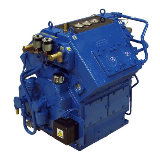
GENERAL DESCRIPTION AND OPERATION PAGE 21 4 GENERAL DESCRIPTION AND OPERATION 4.1 CONFIGURATION The 5217.2.IA water-cooled compressor is of the four cylinder, single acting, two stage, 90°-vee configuration which provides complete primary balance. 4.2 LUBRICATION The forced feed system is shown on following page. The specified lubricant must be used at all times to ensure safe and efficient operation with minimum wear and maximum protection against moist air corrosion. -
Page 24: Lubrication Schematic Flow Diagram
GENERAL DESCRIPTION AND OPERATION PAGE 22 4.6 LUBRICATION SCHEMATIC FLOW DIAGRAM... -
Page 25: Running Gear
GENERAL DESCRIPTION AND OPERATION PAGE 23 4.7 RUNNING GEAR Big and small end bearings along with main bearing bushes are all replaceable. 4.8 VALVES Both stage valves are of the flat, low lift, multi-ported type and combine suction and delivery functions. All valves are easily accessible for maintenance and replacement when required. - Page 26 GENERAL DESCRIPTION AND OPERATION PAGE 24...
-
Page 27: Leading Particulars
LEADING PARTICULARS PAGE 25 5 LEADING PARTICULARS 5.1 UNIT DESIGNATION Model ............................. 5217.2.IA 5.2 GENERAL Type ..................Four cylinder, 2 stage, vee configuration Cooling ............................Water Direction of rotation, viewed from drive end ..............Anti-clockwise Number of valves ............. One combined suction and delivery per cylinder Type of valve ...................... -
Page 28: Running Clearances
LEADING PARTICULARS PAGE 26 5.10 RUNNING CLEARANCES Description Stage As fitted Max. Permissible (mm) (mm) Piston Vertical Clearance 0.25/1.0 0.25/1.0 Piston Ring Gaps 0.15/0.33 0.08/0.20 Piston Ring Axial Width Clearance 0.05/0.1 0.15 0.05/0.1 0.15 Small End Bearing Diametral Clearance In Conn Rod 0.022/0.053 Needle Roller In Piston... -
Page 29: Installation
INSTALLATION PAGE 27 6 INSTALLATION 6.1 HANDLING When using the compressor and motor eyebolts as the slinging attachment, it is essential that a spreader is used. The lift should always be made vertical, as inclined loadings drastically reduce the strength of the eyebolts. -
Page 30: Mounting
INSTALLATION PAGE 28 6.3 MOUNTING Under normal circumstances a special foundation is unnecessary but verification must be obtained that the support floor is structurally adequate as well as flat and level. If installed adjacent to vibrating machinery it may be necessary to bolt down the isolation pads but when tightening, ensure the isolation pads are not distorted. -
Page 31: Cooling
INSTALLATION PAGE 29 6.6 COOLING Satisfactory compressor operation depends on correct cooling, which requires positive circulation of cool, clean water, free from suspended particles. Check water is flowing in mains installations or, if closed circuit, that radiator is full. It is recommended that a filter be fitted in the inlet water line (mains). Maximum permitted water pressure within the compressor is 5 bar equivalent to 52 metres of water head. -
Page 32: Recommended Ancillaries Summary
INSTALLATION PAGE 30 6.8 RECOMMENDED ANCILLARIES SUMMARY Flexible pipe at final delivery. Overload trips. Water inlet and outlet thermometers. Water flow control. Separators and drain traps. Non-return valves. -
Page 33: Commissioning Or Recommissioning
COMMISSIONING OR RECOMMISSIONING PAGE 31 7 COMMISSIONING OR RECOMMISSIONING W A R N I N G :- BEFORE OPERATING THIS EQUIPMENT USERS SHOULD BE MADE AWARE OF AND ENSURE COMPLIANCE WITH THE HEALTH AND SAFETY REGULATIONS APPROPRIATE TO THIS CLASS OF WORK. -
Page 34: Start-Up Procedure
COMMISSIONING OR RECOMMISSIONING PAGE 32 7.2 START-UP PROCEDURE Check radiator is topped up on radiator sets or water is flowing in correct volume in mains water installations. Operate starter. Check immediately that the direction of rotation is counter-clockwise looking on driving end. Check that oil pressure is above 2 bar. -
Page 35: Operation And Routine Maintenance
OPERATION AND ROUTINE MAINTENANCE PAGE 33 8 OPERATION AND ROUTINE MAINTENANCE 8.1 OPERATION AND GENERAL MAINTENANCE The commissioning procedure should be used:– (a) For the first commissioning run (b) Following overhaul (c) After standing idle for an extended period External cleanliness of the compressor pipework and jointing is imperative in order that any leakages may be readily detected. - Page 36 OPERATION AND ROUTINE MAINTENANCE PAGE 34...
-
Page 37: Maintenance Schedule
MAINTENANCE SCHEDULE PAGE 35 9 MAINTENANCE SCHEDULE W A R N I N G : BEFORE PROCEEDING WITH MAINTENANCE ON THE COMPRESSOR IT MUST BE STOPPED AND ISOLATED ELECTRICALLY AND MECHANICALLY AND VISIBLE WARNING NOTICES DISPLAYED. IN ADDITION ALL INTERNAL PRESSURE MUST BE RELEASED WITH THE UNIT ISOLATED FROM THE SUPPLY AND STORAGE RESERVOIR AND THE WATER SUPPLY SHUT OFF. -
Page 38: Service Plan
MAINTENANCE SCHEDULE PAGE 36 9.6 SERVICE PLAN .6 SERVICE PLAN Service Kit Number Service Plan - 5217 Industrial Air 12 Months From Installation/Last Service Or Task Description Parts Provided Change air intake element (air X X X X X X Suction filter element compressor only) X X X X X X X 2... - Page 39 MAINTENANCE SCHEDULE PAGE 37 Service Kit Number Service Plan - 5217 Industrial Air 12 Months From Installation/Last Service Or Task Description Parts Provided Big end bolts X 25 Service water valve-U231.F Service kit FITTED X 26 Replace main bearing & oil seal D/E Bearing bush Joint Oil seal...
- Page 40 MAINTENANCE SCHEDULE PAGE 38 Service Kit Number Service Plan - 5217 Industrial Air 12 Months From Installation/Last Service Or Task Description Parts Provided 1st stage 2nd stage Test pressure gauges 1st stage 2nd stage Test temperature switches 1st stage Final stage Test low oil pressure switch L.O.P Test non return valve...
-
Page 41: Dismantling And Reassembly Of Valves
DISMANTLING AND REASSEMBLY OF VALVES PAGE 39 10 DISMANTLING AND REASSEMBLY OF VALVES 10.1 GENERAL Keep a spare oiled and maintained set of valve units in store for quick compressor servicing. Valves when removed should have only a thin carbon layer and be slightly moist with oil. Valve maintenance is a simple procedure but the following guidelines should be observed. -
Page 42: Valve Replacement
DISMANTLING AND REASSEMBLY OF VALVES PAGE 40 10.5 VALVE REPLACEMENT 0.5 VALVE REPLACEMENT Ensure valve pocket is clean before replacing valve assembly. Ensure valve beds properly as a slight misfit will entail the loss of air. Check valve cover for cleanliness before reassembly. Renew 'O' rings lightly greasing before fitting. -
Page 43: Valve Reassembly
DISMANTLING AND REASSEMBLY OF VALVES PAGE 41 10.6 VALVE REASSEMBLY 10.6.1 FIRST STAGE CONCENTRIC VALVE Place upper valve body (11) on open vice jaws or a tubular support (an upturned aerosol can top or similar object will be suitable for this purpose), with locating pegs (7) and (8) uppermost. Place suction plate (4) on the valve body, engaging it with peg (7). - Page 44 DISMANTLING AND REASSEMBLY OF VALVES PAGE 42...
-
Page 45: Fault Guide
FAULT GUIDE PAGE 43 11 FAULT GUIDE IMPORTANT THE WORK DETAILED IN THE FOLLOWING GUIDE MUST ONLY UNDERTAKEN SUITABLY TRAINED AND QUALIFIED PERSONEL. WARNING BEFORE PROCEEDING WITH ANY MAINTENANCE ON THE COMPRESSOR IT MUST BE STOPPED ISOLATED ELECTRICALLY AND MECHANICALLY, COMPRESSOR GAS INLET AND OUTLET VALVES CLOSED AND VISIBLE WARNING NOTICES DISPLAYED. -
Page 46: Will Not Start
FAULT GUIDE PAGE 44 Symptom Fault Recommendation(s) Check power to starter. Electrical fault. Check emergency stop buttons are released. 11.1 WILL NOT Check for previous stop fault condition – high START air / gas temperature switches, low oil pressure switch etc. Check fuses within starter. -
Page 47: Safety Valve Blowing
FAULT GUIDE PAGE 45 Symptom Fault Recommendation(s) Verify discharge pipework bore is large enough, Final stage safety has a minimum of bends at the largest possible valve blowing. 11.4 SAFETY radius. VALVE Ensure discharge non-return valves are fitted the right way round and functioning correctly. BLOWING Ensure pressure maintaining valve is functioning correctly. -
Page 48: Stops Suddenly
FAULT GUIDE PAGE 46 Symptom Fault Recommendation(s) Check switch. Low oil pressure Check compressor rotation. switch operating. 11.5 STOPS Check oil level. SUDDENLY Check & clean oil strainer. Renew oil filter. Renew oil pump. Check condition of main, small end and big end bearings. -
Page 49: Low Oil Pressure
FAULT GUIDE PAGE 47 Symptom Fault Recommendation(s) Fit new oil filter element. Oil filter blocked. Check bearing clearances Worn bearings. 11.7 LOW OIL Trace and rectify Loose pipe PRESSURE connections. Examine gasket, replace if necessary, position Bearing end plate correctly. gasket distorted partially blocking suction port... - Page 50 FAULT GUIDE PAGE 48...
-
Page 51: Parts List
PARTS LIST PAGE 49 12 PARTS LIST How to order spares IN ORDER TO AVOID UNNECESSARY DELAY, PLEASE QUOTE:- 1. Complete invoicing and shipping address 2. Machine Model Reference No. 3. Machine No. 4. Item Reference 5. Part No. 6. Description 7. - Page 52 PARTS LIST PAGE 50 05.7 02/03 05.3 05.4 05.9 05.7 05.8 05.8 05.1 05.10 05.11 05.2 05.6 05.5 05.3 02/03 01 -09 CRANKCASE...
-
Page 53: Crankcase Parts
PARTS LIST PAGE 51 12.1 CRANKCASE PARTS ITEM REF DESCRIPTION PART N° N° OFF BEARING HOUSING D/E D101671 Bush C200020 Bearing Housing D100009 Joint D100355 Oil Seal 98505.1002 CRANKCASE E61605 Stud D66720.12.53 Stud D66720.12.248 Crankcase E60037 Plug PS1068.5 95111.7 Oil Level Gauge 98281.1002 Washer Fibre with item 'e'... - Page 54 PARTS LIST PAGE 52 .2.2 .2.1 .1.1 .1.2 16.2 .1.2 .1.1 16.2 11/12 .1 .2 16.1 16.5 16.3 16.4 11/12 .1.1 .1.2 .1.1 .1 2.2 .2.3 .2.1 16.6/16.7 RUNNING GEAR 10 - 19...
-
Page 55: Running Gear Parts
PARTS LIST PAGE 53 12.2 RUNNING GEAR PARTS 2.2 RUNNING GEAR PARTS ITEM REF DESCRIPTION PART N° N° OFF CRANKSHAFT D100008.100 Crankshaft D100008 .1.1 Grub Screw 95074.47 95301.63 PISTON 1st STAGE D101675 Piston D100014 .1.1 Gudgeon Pin C200028 .1.2 Circlip 95650.25 Piston Ring Set 98477.1109... - Page 56 PARTS LIST PAGE 54 21/22 25.1 25.3/25.4 21/22 .2.1 24.1 .2.2 .2.3 24.3 24.2 25.2 21/22 .7 .3 .4 .1 21/22 STAGE CYLINDER 20 - 29...
-
Page 57: 1St Stage Cylinder Parts
PARTS LIST PAGE 55 12.3 1ST STAGE CYLINDER PARTS ITEM REF DESCRIPTION PART N° N° OFF CYLINDER ASSY E60040.50 Joint C200631 Cylinder E60040 .2.1 Stud M10 X 30 D66720.10.45 .2.2 Stud M10 X 70 D66720.10.85 .2.3 Stud M10 X 140 D66720.10.155 Plug PS1068.5... - Page 58 PARTS LIST PAGE 56 31/32 36.3 33 .1 31.9 31.8 .2.1 .2.2 36.2 31/32 36.1 STAGE CYLINDER 30 - 39...
-
Page 59: 2Nd Stage Cylinder Parts
PARTS LIST PAGE 57 12.4 2ND STAGE CYLINDER PARTS ITEM REF DESCRIPTION PART N° N° OFF CYLINDER ASSY E60041.50 Joint C200866 Cylinder E60041 .2.1 Stud M10 X 30 D66720.10.45 .2.2 Stud M12X 100 D66720.12.118 Plug PS1068.5 Seal PS.1322.6 Setscrew 95018.272 95111.6 95111.7 Dowel... - Page 60 PARTS LIST PAGE 58 45.17 45.14 45.23 .4 .6 .7 45.1 45.23 STAGE 43.7 43.6 45.7 45.5 45.13 45.21 45.11 45.4 45.12 45.17 45.16 45.24 45.23 45.15 .3 .7 .1 45.23 45.20 45.6 45.22 45.16 45.24 STAGE .6 .5 45.8 45.2 45.9 45.3...
-
Page 61: 1St & 2Nd Stage Cooler Parts
PARTS LIST PAGE 59 12.5 1ST & 2ND STAGE COOLER PARTS 2.5 1ST & 2ND STAGE COOLER PARTS ITEM REF DESCRIPTION PART N° N° OFF COOLER ASSY 1st STAGE C204070 Tube plate C204062 Cooler tubes C200675.3 Joint C200678 Stud M10 X 140 D67972.10.155 Stud M10 X 60 D67972.10.75... - Page 62 PARTS LIST PAGE 60 58.13 58.12 58.11 58.1 58.5 56/57 58.8 58.10 58.6 58.7 58.4 58.9 52/ 53 .2 .3 .1 .5 58.2 TYPICAL STANDARD PRESSURE & TEMPERATURE GAUGES 50 - 59...
-
Page 63: Pressure Gauge Parts
PARTS LIST PAGE 61 12.6 PRESSURE GAUGE PARTS ITEM REF DESCRIPTION PART N° N° OFF GAUGE PIPE ASSY OIL C201967.9 Adaptor 4mm X 1/4 BSP 98156.1294 Tube Nut 4mm 98156.1315 Tube Sleeve 4mm 98156.1386 Pipe Nylon 4mm X 150mm 98617.5104 Seal 98660.1153 GAUGE PIPE ASSY 1st STAGE... - Page 64 PARTS LIST PAGE 62 .3 66 67.9 67.10 67.8 67.1 67.2 67.11 67.3 67.7 67.4 67.6 67.5 .6 65 62/63 60 -69 LUBRICATION...
-
Page 65: Lubrication Parts
PARTS LIST PAGE 63 12.7 LUBRICATION PARTS ITEM REF DESCRIPTION PART N° N° OFF OIL SUCTION PIPE ASSY C201966.1 Suction Pipe PS2081 Coupling 98156.1054 OIL TRANSFER PIPE ASSY C201966.2 Pipe CU 10 X 762mm M3130.1008 Coupling 98156.1050 OIL PRESS SWITCH PIPE ASSY C201966.3 Pipe Steel 6 X 1000mm M.3130.0603... - Page 66 PARTS LIST PAGE 64 72 .2 74.2 74.6 74.8 74.7 74.8 74.6 74.3 74.1 74.4 74.5 DRAIN VALVE & PIPING 70 - 79...
-
Page 67: Drain Valve & Piping Parts
PARTS LIST PAGE 65 12.8 DRAIN VALVE & PIPING PARTS ITEM REF DESCRIPTION PART N° N° OFF SEPR. DRAIN PIPE ASSY 1st STG C203890 Pipe Copper 20mm X 610mm M3201.2017 Coupling 98156.1060 Coupling 98156.1158 Seal 98660.1156 SEPR. DRAIN PIPE ASSY 2nd STG C203891 Pipe Steel 10mm X 1000mm M.3089.1008... - Page 68 PARTS LIST PAGE 66 83.2 83.1 83.5 83.6 83.3 83.4 84.1 EXTERNAL COMPONENTS 80 - 89...
-
Page 69: External Components Parts
PARTS LIST PAGE 67 12.9 EXTERNAL COMPONENTS PARTS 2.9 EXTERNAL COMPONENTS PARTS ITEM REF DESCRIPTION PART N° N° OFF SUCTION PIPE ASSY 2nd STAGE C203887. Copper 20mm X 500mm M3201.2017 Coupling 20mm X 3/4 BSP 98156.1245 Elbow Swivel 2 0mm X 3/4 BSP 98156.1061 Seal 3/4 BSP 98660.1156... - Page 70 PARTS LIST PAGE 68 91.4 91.5 91.6 91.10 91.1 91.3 91.9 91.8 91.7 91.2 91.11 91.12 91.13 91.11 91.12 91.13 91.18 91.26 91.27 91.28 91.15 91.21 91.23 91.24 91.14 91.16 91.22 91.17 91.19 91.20 91.14 TYPICAL DRIVE ARRANGEMENTS...
-
Page 71: Drive Parts
PARTS LIST PAGE 69 12.10 DRIVE PARTS ITEM REF DESCRIPTION PART N° N° OFF 91.1 FLYWHEEL D100301 91.2 BELL HOUSING E60021 91.3 DRIVEN HALF COUPLING C11359.128 91.4 COVER PLATE PS.2289.1 91.5 SETSCREW Bell housing to compressor 95001.315 91.6 SETSCREW Motor to bell housing 95001.345 91.7 CAPSCREW Coupling to flywheel... - Page 72 PARTS LIST PAGE 70 STAGE CONCENTRIC VALVE 93 - 95...
-
Page 73: 1St Stage Concentric Valve Parts
PARTS LIST PAGE 71 12.11 1ST STAGE CONCENTRIC VALVE PARTS ITEM REF DESCRIPTION PART N° N° OFF 93.3 CONCENTRIC VALVE 1st Stage 98650.1841 VALVE MAINTENANCE KIT 98650.1842 'O' Ring 98504.1006 'O' Ring 98504.1193 98650.1040 Suction Plate (Small) 98651.1026 Lift washer 98651.1027 Lift washer 98651.1028... - Page 74 PARTS LIST PAGE 72 STAGE CONCENTRIC VALVE 96 - 97...
-
Page 75: 2Nd Stage Concentric Valve Parts
PARTS LIST PAGE 73 12.12 2ND STAGE CONCENTRIC VALVE PARTS ITEM REF DESCRIPTION PART N° N° OFF 96.1 CONCENTRIC VALVE 2nd Stage 98650.1099 VALVE MAINTENANCE KIT 98650.1578 'O' Ring 98504.1005 98650.1050 Suction Plate (Small) 98650.1103 Spring Plate (Small) 98650.1104 Delivery Plate (Large) 98650.1105 Spring Plate (Large) 98650.1106... - Page 76 PARTS LIST PAGE 74 & 2 STAGE 98.8 98.7 98.5 .3 .4 1.4 1.3 1.2 .1.1 98.6 .3 .4 2.1 2.2 2.3 2.4 99.8 98.7 98.5 98.8 OPTIONAL 99.6 99.5 99.2 99.3 99.7 1.1 1.2 1.3 1.4 99.2 99.4 99.9 98-99 DIAPHRAGM DRAIN VALVE...
-
Page 77: Diaphragm Drain Valves Parts
PARTS LIST PAGE 75 12.13 DIAPHRAGM DRAIN VALVES PARTS ITEM REF DESCRIPTION PART N° N° OFF 98.1 D DRAIN VALVE 1st & 2nd Stg U.334.M MAINTENANCE KIT 98650.1531 Valve Assy 1st Stage C201980 .1.1 Valve Seat C200842 .1.2 Valve C201976 .1.3 Mushroom Plate C201978... -
Page 78: Joint Kit
PARTS LIST PAGE 76 12.14 JOINT KIT DESCRIPTION PART N° N° OFF OVERHAUL JOINT KIT 98504.1077 JOINT COVER PLATE C200071 JOINT 1st STAGE SUCTION C200205 JOINT 1st STAGE CYL TO CRANKCASE C200631 JOINT 1st STAGE COOLER COVER O/E C200678 JOINT 2nd STAGE COOLER COVER O/E C200679 JOINT 2nd STAGE COOLER COVER D/E C200682... -
Page 79: Ddv Maintenance Kit U334K & L
PARTS LIST PAGE 77 12.17 DDV MAINTENANCE KIT U334K & L DESCRIPTION PART N° N° OFF MAINTENANCE KIT U334/M 98650.1531 Valve/Valve Plate Assy C201980 Valve Seat C200842 Valve/Valve Plate Assy C201981 Valve Seat C201417 12.18 SERVICE KIT FOR DDV'S DESCRIPTION PART N°... - Page 80 PARTS LIST PAGE 78...
-
Page 81: Ancillary Parts
ANCILLARY PARTS PAGE 79 13 ANCILLARY PARTS 13.1 TEMPERATURE CONTROLLER – APP090 THERMOMETER SWITCHES C202556, C202749, C202960 & C202964 98288.1093, 98288.1094 & 98288.1215 THESE THERMOMETER SWITCHES ARE SET TO THE FIGURES QUOTED BELOW, THE FOLLOWING INFORMATION IS FOR SETTING INFORMATION ONLY, IF THE TEMPERATURE SWITCH HAS TO BE REPLACED OR RE-ADJUSTED. - Page 82 ANCILLARY PARTS PAGE 80 CONTROLLER TRIP POINTER USED ON PART No STOP SETTING °C COMPRESSOR MODEL C202556.1 5236.1 C202556.2 5212 C202556.3 5336,5415 C202556.4 5215 & 5217 C202556.5 5236.2,5315 C202556.6 5415E5317,5417.5417N C202556.7 5436(CU TUBES) C202556.8 5436.1 &.2,5436H,5436N,5436SN & 5437 C202749.1 5280 C202749.2 5280 C202749.3...
-
Page 83: Safety Valve - App167
ANCILLARY PARTS PAGE 81 13.2 SAFETY VALVE – APP167 INSTALLATION AND OPERATING INSTRUCTIONS SAFETY VALVES INTRODUCTION Due consideration should be taken of climatic. Process or other conditions which might adversely affect the performance of the safety valve. Installation must be undertaken by qualified technicians and to good engineering practice. - Page 84 ANCILLARY PARTS PAGE 82 FUNCTIONAL TESTING Once installed in service. Valves should be tested at least once every six months to ensure free movement of parts. This should be carried out by operating the easing gear when the valve is under a pressure of not less than 75'% of the set pressure.
-
Page 85: Solenoid Valve Ddv - App138
ANCILLARY PARTS PAGE 83 13.3 SOLENOID VALVE DDV – APP138 3.3 SOLENOID VALVE DDV – APP138 3 WAY SOLENOID VALVE PS2197 OPERATION 3 way normally closed energise to open, continuous duty. On starting the solenoid valve opens (energised) this operates the diaphragms which in turn closes the valves within the D.D.Vs. -
Page 86: Anti Vibration Mounts - App003
ANCILLARY PARTS PAGE 84 13.4 ANTI VIBRATION MOUNTS – APP003 AVA TYPE PART NUMBERS VARIOUS PREVENTIVE MAINTENANCE After installation and initial running in. Record height dimension (H) of each mount. After a week or 100 hours running time recheck and record dimension (H) Check this dimension every 3 to 6 months depending on usage i.e. -
Page 87: Water Pump Drive - App074
ANCILLARY PARTS PAGE 85 13.5 WATER PUMP DRIVE – APP074 3.5 WATER PUMP DRIVE – APP074 WATER PUMP DRIVE 5212, 5215, 5217, 5317 & 5417 MK2 OUTLET INLET Item No Part No Description No Off C200780/2 Fitting - water pump drive C200781 Gasket - water pump C200870... -
Page 88: Expansion Tank Cooling Water System - App076-5217
ANCILLARY PARTS PAGE 86 13.6 EXPANSION TANK COOLING WATER SYSTEM – APP076-5217 3.6 EXPANSION TANK COOLING WATER SYSTEM – APP076-5217 EXPANSION TANK WATER COOLING SYSTEM SPECIAL INSTRUCTIONS FOR FILLING COMPRESSOR 5215 & 5217 5217 MK2 ILLUSTRATED FRESH WATER COOLING SYSTEM VENT PIPE FILLER CAP EXPANSION... - Page 89 ANCILLARY PARTS PAGE 87 EXPANSION TANK WATER COOLING SYSTEM SPECIAL INSTRUCTIONS FOR FILLING COMPRESSOR BEFORE INITIAL STARTING FILLING AND BLEEDING THE WATER SYSTEM. CAPACITY APPROXIMATELY 5215 & 5217 - 40 LITRES. See before starting procedure in HANDBOOK in conjunction with the following. 1.
-
Page 90: Pressure Gauges - App070
ANCILLARY PARTS PAGE 88 13.7 PRESSURE GAUGES – APP070 PRESSURE GAUGES GENERAL The pressure gauge should be installed such as to avoid exposure to heat and vibration and to enable easy observation of the dial indication. IMPORTANT It is common practise to install the pressure gauge without an isolating device, so to facilitate calibration or replacement the system must be de pressurised before any work is carried out. -
Page 91: Flexible Hose - App248
ANCILLARY PARTS PAGE 89 13.8 FLEXIBLE HOSE – APP248 3.8 FLEXIBLE HOSE – APP248 APP248 FLEXIBLE HIGH PRESSURE AIR/GAS HOSES GENERAL IF A FLEXIBLE DELIVERY AIR/GAS HOSE FAILS REPLACE THE WHOLE UNIT, CHECK OTHERS REPLACE AS NECESSARY. PREVENTIVE MAINTENANCE Every 3 months, check the following:- 1) Outer casing for cracks, defects and leaks. - Page 92 ANCILLARY PARTS PAGE 90...
-
Page 93: Standard Wiring Terminal Numbers
STANDARD WIRING TERMINAL NUMBERS PAGE 91 14 STANDARD WIRING TERMINAL NUMBERS WHEN THE MOTOR AND / OR STANDARD COMPRESSOR CONTROL DEVICES HAVE BEEN PRE- WIRED INTO LOCAL MARSHALLING BOXES OR DIRECTLY INTO A STARTER / CONTROL PANEL, THE FOLLOWING TERMINAL NUMBERS ARE USED. ALL OTHER TERMINALS ARE AS SPECIFIC CONTRACT DRAWINGS STANDARD TERMINAL IDENTIFICATION FOR SET WIRING TERMINAL... - Page 94 STANDARD WIRING TERMINAL NUMBERS PAGE 92...
- Page 96 WARNING The use of replacement parts or lubricating oils not supplied, recommended or approved by Reavell, may lead to failure in service which would not be covered by the warranty. Any unauthorised modifications or failures to maintain this equipment is accordance with the manufacturer’s maintenance instructions may make it unsafe.
Need help?
Do you have a question about the Reavell H5000 Series and is the answer not in the manual?
Questions and answers