Table of Contents
Advertisement
Quick Links
Advertisement
Table of Contents

Related Manuals for Ada PLATINUM II


Summary of Contents for Ada PLATINUM II
- Page 1 PLATINUM II ZONE CONTROL SYSTEM MOTION SENSOR/TIMER...
-
Page 3: Table Of Contents
13. Motion Sensor with Add-On Timer Configuration 14. Motion Sensor Configuration - No Zones 15. Motion Sensor with Add-On Timer Configuration - No Zones 16. System Set Up 17. Timer Function 18. Motion Sensor Function 19. Faults 20. Diagnostics 21. Warranty 22. Notes PLATINUM II... -
Page 4: Precautions
PRECAUTIONS 1. Precautions Refer to these installation instructions before commencing the installation or service of this product. WARNING This product should be installed and set up by qualified personnel. To reduce the risk of fire, electric shock or product damage: DO NOT expose to rain or moisture of any kind DO NOT place articles filled with water on or near this appliance DO NOT remove covers –... -
Page 5: Components Supplied - Sips Kit
SIPS01 Control Box A/C Link Cable (9m) 240V AC Power Cord Link Cable (15m) 1 x Instruction Manual 4. Components Supplied - Timer Kit TM01 Timer A/C Link Cable (9m) 2 x Fixing Kit 1 x Instruction Manual PLATINUM II... -
Page 6: Components Supplied - Motion Sensor Kit
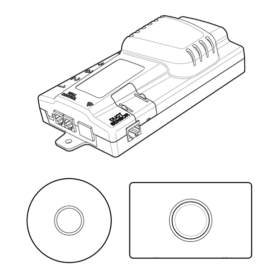
MOUNTING THE TIMER 5. Components Supplied - Motion Sensor Kit MS01 Motion Sensor Cable (9m) 2 x Fixing Kit 1 x Instruction Manual 6. Mounting the Timer NOTE: To use the Timer with an A/C, the A/C must have external control input. Power is supplied from the A/C indoor unit - refer to A/C unit wiring diagram. - Page 7 MOUNTING THE TIMER To A/C Cover Plate Mounting Screw Front Plate To remove Cover Plate once assembled onto the wall, use a small flat head screwdriver in the locations shown to pry Cover Plate off of the Front Plate. PLATINUM II...
-
Page 8: Wiring Diagram
WIRING DIAGRAM 7. Wiring Diagram Pin connections from Timer and/or SIPS Control Box for A/C control as shown (colours are as supplied cable). PIN 2 (GREEN) PIN 3 (ORANGE/WHITE) PIN 1 PIN 5 PIN 6 (BLUE/WHITE) PIN 6 (BLUE) PIN 1 GREEN/WHITE NOT USED PIN 2 GREEN PIN 3 ORANGE/WHITE... -
Page 9: Multiple Timers Using Sips
Zone Damper on the RMC04. Ensure all connections are made before powering on the system. Mounting Screw 240VAC Timer Cables Power Cord SIPS Control Box Link Cable to RMC04 To A/C Touch Screen Cable (optional) LED light indicates power PLATINUM II... -
Page 10: Multiple Timer Configuration
Relief Zones, so that if all the Zones are closed, the A/C will not be damaged. For the Platinum II system to know if it is in Heating or Cooling Mode requires an Auto system configuration with the use of a Duct Sensor and temperature Sensors in each room. - Page 11 MULTIPLE TIMER FUNCTION PLATINUM II...
-
Page 12: Mounting The Motion Sensor
MOUNTING THE MOTION SENSOR 10. Mounting the Motion Sensor Choose an appropriate position on the ceiling to mount the Motion Sensor. Ÿ Mark and cut out hole in ceiling as shown, then use the Mounting Plate to Ÿ mark holes for the screw fixings. Use the appropriate supplied fixings for the ceiling material. -
Page 13: Multiple Motion Sensors Using Sips
Zone Damper on the RMC04. Ensure all connections are made before powering on the system. Mounting Screw Motion Sensor 240VAC Cables Power Cord SIPS Control Box Link Cable to RMC04 To A/C Touch Screen Cable (optional) LED light indicates power PLATINUM II... -
Page 14: Motion Sensor Configuration
MOTION SENSOR CONFIGURATION 12. Motion Sensor Configuration When configured correctly, using Motion Sensors eliminates the requirement for unused Zones to be air-conditioned. For a Manual System, in any Zone every 20 minutes without motion detection, the Zone Damper closes from 100% to 70%, then 30%, then fully closed. If motion is detected, the Zone Damper resets to its original position. - Page 15 MOTION SENSOR CONFIGURATION PLATINUM II...
- Page 16 MOTION SENSOR CONFIGURATION NOTE: Although the maximum number of Motion Sensors that can be used is 8, Motion Sensors can be used on systems with more than 8 Zones by configuring the system as shown. Motion Sensors can only be used on Zones 1-8. MOTION SENSOR/TIMER SET UP...
-
Page 17: Motion Sensor With Add-On Timer Configuration
Motion Sensor functionality will operate for as long as the Timer is active. If the Timer is switched off or reaches the end of the countdown period, the Motion Sensors will not be active. Refer configuration diagram below for a typical system design. PLATINUM II... -
Page 18: Motion Sensor Configuration - No Zones
MOTION SENSOR CONFIGURATION - NO ZONES 14. Motion Sensor Configuration - No Zones One or more Motion Sensors can be used to directly switch on/off an A/C unit that does not utilize a Zone system. Up to 8 Motion Sensors may be used. NOTE: To use the Motion Sensors with an A/C, the A/C must have external control input. -
Page 19: Motion Sensor With Add-On Timer Configuration - No Zones
Motion Sensors will not be active. Refer configuration diagram below for a typical system design. Timer 1 Timer 2 Timer 3 Motion Sensor 1 Motion Sensor 1 Motion Sensor 2 Motion Sensor 2 Motion Sensor 3 Motion Sensor 3 SIPS To A/C PLATINUM II... -
Page 20: System Set Up
SYSTEM SET UP 16. System Set Up Motion Sensors and/or Timers will be automatically detected only after the initial set up process has been completed. After the initial set up process, information related to Motion Sensors and/or Timers is accessed from the System Set Up screen by pressing the settings icon on the top right corner of Base Screen... - Page 21 SYSTEM SET UP Zones with Motion Sensors and/or Timers are highlighted in green. If there is a fault with a Motion Sensor or Timer, it will be highlighted in red. PLATINUM II PLATINUM II...
-
Page 22: Timer Function
SYSTEM SET UP 17. Timer Function In a Manual system the Base screen will show a ‘T’ when a Timer has deactivated a Zone and indicate it is in an OFF state. The arrow icons will not function. In an Auto system, the Base screen will show also show a ‘T’, the Auto/Manual icons will be blanked out and the arrow... -
Page 23: Faults
If a Motion Sensor and a Timer are both used for a Zone, the ‘T’ will override ‘M’. 19. Faults If there is a fault with a SIPS Control Box it will be highlighted as shown. PLATINUM II... - Page 24 SYSTEM SET UP A fault for a Motion Sensor will be highlighted as shown. A fault for a Timer will be highlighted as shown. MOTION SENSOR/TIMER SET UP...
-
Page 25: Diagnostics
SYSTEM SET UP 20. Diagnostics The Diagnostics screen will show M0, M1, M2 or M3 to indicate the current Motion Sensor activation level. The Diagnostics screen will show T0 or T1 to indicate the status of a Timer. PLATINUM II... -
Page 26: Warranty
This warranty is not transferrable and is only available to the original purchaser. 22. Notes All service to the Platinum II system must be carried out by an approved Air Diffusion Agencies service technician, and must not be done by unqualified personnel. Repairs carried out by unqualified personnel will void warranty. - Page 28 www.airdiffusion.com.au ADAPMT1119...
Need help?
Do you have a question about the PLATINUM II and is the answer not in the manual?
Questions and answers