Advertisement
Quick Links
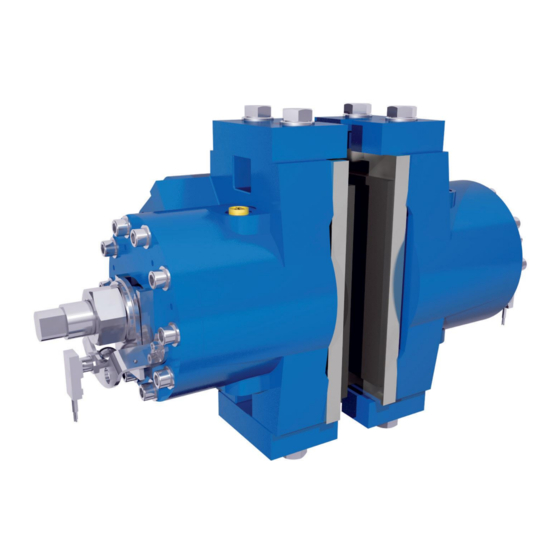
HYDRAULIC CALLIPER TYPE NHCD-1400
Instructions for assembly, adjustment and maintenance
Technical data sheet number:
BC.TDS.00025I
Author:
Unitzer Bilbao / Oscar Lucio
Revised by:
Sales Department
Date:
September 2012
Date Rev.01.
-
Aplicación Nuevas Tecnologías, ANTEC S.A.
Ramón y Cajal, 74 – 48.920 Portugalete (Bizkaia) - Spain.
Tel.: 0034 94 496 50 11
Fax: 0034 94 496 53 37
After Sales Service: sales@antecsa.com
Page 1-42
www.antecsa.com
Advertisement

Related Manuals for Antec NHCD-1400


Summary of Contents for Antec NHCD-1400
- Page 1 HYDRAULIC CALLIPER TYPE NHCD-1400 Instructions for assembly, adjustment and maintenance Technical data sheet number: BC.TDS.00025I Author: Unitzer Bilbao / Oscar Lucio Revised by: Sales Department Date: September 2012 Date Rev.01. Aplicación Nuevas Tecnologías, ANTEC S.A. Ramón y Cajal, 74 – 48.920 Portugalete (Bizkaia) - Spain.
- Page 2 HYDRAULIC CALLIPER TYPE NHCD-1400 Instructions for assembly, adjustment and maintenance 1. INTRODUCTION. Page 3 Page 3 1.1. WHO IS THE TARGET AUDIENCE? Page 3 1.2. SAFETY INSTRUCTIONS. Page 5 1.3. GENERAL ASPECTS. 2. BRAKE DELIVERY AND ASSEMBLY. Page 12 Page 12 2.1.
-
Page 3: Safety Instructions
Due to ongoing improvements to our brake designs, your brake may differ slightly from the one described in NOTE this manual. ANTEC reserves the right to make any changes deemed necessary. 1.2. SAFETY INSTRUCTIONS. Various symbols appear throughout this manual, which highlight the importance of the subject section. - Page 4 2-. Always keep warning signs (if any) on the brake in good condition and adhere to them. During repairs or maintenance, place a warning sign to inform other workers that an ANTEC brake is being repaired in that machine, and that the power supply has been disconnected, if applicable.
-
Page 5: General Aspects
The NHCD-1400 brakes, are failsafe emergency brakes, in other words they brake using springs when there is no hydraulic pressure. These brakes consist of two half-callipers mounted symmetrically to the plane of the disc on which they act. - Page 6 HYDRAULIC CALLIPER TYPE NHCD-1400 Instructions for assembly, adjustment and maintenance The braking torque of a NHCD-1400 brake, depends directly on the braking force described in the previous table (for each brake) and the outside diameter of the disc on which the brake acts.
- Page 7 HYDRAULIC CALLIPER TYPE NHCD-1400 Instructions for assembly, adjustment and maintenance Power 3/8”G Power 3/8”G T.D.S.: BC.TDS.00025I Rev.0.: September - 2012 www.antecsa.com Page 7-42...
- Page 8 HYDRAULIC CALLIPER TYPE NHCD-1400 Instructions for assembly, adjustment and maintenance The NHCD-1400 brakes are comprised of the parts listed below: BRAKE PARTS SET Number Name Quantity MAIN BODY PISTON COVER SPACER ADJUSTMENT SCREW LOCKING BACKSTOP ACTUATOR SENSOR BRACKET LINING PLATE...
- Page 9 HYDRAULIC CALLIPER TYPE NHCD-1400 Instructions for assembly, adjustment and maintenance ASSEMBLY T.D.S.: BC.TDS.00025I Rev.0.: September - 2012 www.antecsa.com Page 9-42...
-
Page 10: Assembly Breakdown
HYDRAULIC CALLIPER TYPE NHCD-1400 Instructions for assembly, adjustment and maintenance ASSEMBLY BREAKDOWN Backstop position with locked brake T.D.S.: BC.TDS.00025I Rev.0.: September - 2012 www.antecsa.com Page 10-42... - Page 11 HYDRAULIC CALLIPER TYPE NHCD-1400 Instructions for assembly, adjustment and maintenance Optional Backstop position with unlocked brake T.D.S.: BC.TDS.00025I Rev.0.: September - 2012 www.antecsa.com Page 11-42...
- Page 12 The NHCD-1400 callipers are supplied without pressure, with fully distended springs. Antec certifies that the NHCD-1400 brakes have been tested on the company's test benches at its facilities using the proper operating oil. The inside brake parts are lubricated so that the brake will not suffer corrosion while being transported to the customer's facilities and during the subsequent assembly process.
-
Page 13: Assembly Procedure
2.3. ASSEMBLY PROCEDURE. To assemble the brakes, proceed as follows: 2.3.1. Clean the disc in which you are going to install the NHCD-1400 brake. Any particles could damage the brake and prevent it from working properly. See the first NOTE on disc cleaning in point 2.2. - Page 14 2.3.4. If the brake is supplied with the related bracket, anchor the brake bracket using the corresponding anchoring bolts for each case. 2.3.5. Fit the fastening screws, washers and nuts. Fasten the NHCD-1400 brake to the bracket using the anchoring screws and nuts with the proper torque.
- Page 15 HYDRAULIC CALLIPER TYPE NHCD-1400 Instructions for assembly, adjustment and maintenance 2.3.6. Make the hydraulic feed connections of the brake. Each semi-calliper has 2 connections with a 3/8”G thread for the hydraulic feed. Remove the plugs from the 3/8”G holes to which the hydraulic feed tubing is to be connected. It is recommended to use the lower connection, leaving the upper one free to fit a purging device, and if there is not one, leave the steel plug mounted.
-
Page 16: Brake Maintenance
HYDRAULIC CALLIPER TYPE NHCD-1400 Instructions for assembly, adjustment and maintenance 3. BRAKE MAINTENANCE. NHCD-1400 brake maintenance will consist of regularly checking the following points: 3.1 – Lining wear. When the lining thickness drops below 2 mm at the thinnest point, it needs to be replaced. - Page 17 HYDRAULIC CALLIPER TYPE NHCD-1400 Instructions for assembly, adjustment and maintenance 30-31 4.1.3 Adjust the adjustment screw (marked 5), by tightening or loosening until the distance between the lining and the disc is of 1 mm. We will refer to this distance as the air gap.
- Page 18 HYDRAULIC CALLIPER TYPE NHCD-1400 Instructions for assembly, adjustment and maintenance 4.1.4 Once this opening has been adjusted lock the adjustment screw (marked 5) using the nut (marked 19). 4.1.5 The brake must ALWAYS be adjusted when the brake is installed, there is wear in the lining of 1 mm or the linings are replaced.
- Page 19 Instructions for assembly, adjustment and maintenance 4.2. - Adjustment of sensors In the event that you have an ANTEC brake with brake opening signalling (C.S.A.) and a lining wear sensor (D.D.) (Optional), these must be mounted on the cover as shown in the following diagram.
- Page 20 HYDRAULIC CALLIPER TYPE NHCD-1400 Instructions for assembly, adjustment and maintenance 1 -Black (common) 2 - Brown (NC) 4 - Grey (NO) CURVES 1 Number of operations 2 Resistive circuit 3 Inductive circuit 4 Current in amps How is the opening sensor adjusted?
- Page 21 HYDRAULIC CALLIPER TYPE NHCD-1400 Instructions for assembly, adjustment and maintenance (C.S.A.) When the sensor emits a warning, the operator must know that the following may occur: - The brake is open, with which oil has entered into the hydraulic feed system at the pressure shown in the attached table in point 1.3.
- Page 22 HYDRAULIC CALLIPER TYPE NHCD-1400 Instructions for assembly, adjustment and maintenance By applying the opening pressure for each brake, shown in the attached table in point 1.3. of the instructions, adjust the lining wear sensor (D.D.), to the measurement shown in the following diagram (41.5 mm between the head of the sensor and the strip (marked 8)).
- Page 23 Instructions for assembly, adjustment and maintenance 4.2.3. Lining wear sensor with cable (D.D.) (Optional in the assembly of the brake): Antec brakes have an option for mounting the shoe lining wear detector by inserting two cables into the lining as shown in the following diagram.
- Page 24 When the total thickness of the lining has dropped to 22 mm at any point, in other words, it has worn down by 8 mm, it must be replaced. ANTEC recommends always replacing both brake linings NOTE regardless of whether one or both linings have worn down.
- Page 25 HYDRAULIC CALLIPER TYPE NHCD-1400 Instructions for assembly, adjustment and maintenance To change the linings, proceed as follows: 5.1. Feed the brake at the pressure indicated for each brake in the attached table of point 1.3 of the instructions. 5.2- Maintaining the hydraulic pressure, remove the sensors bracket (marked 9). Then unscrew the nut (marked 19) enough to leave space to mount the backstop lock.
- Page 26 HYDRAULIC CALLIPER TYPE NHCD-1400 Instructions for assembly, adjustment and maintenance 5.3- The linings of both semi-callipers can be changed in the same manner as these can both be dismantled from the sides or from the centre of the brake towards the centre of the disc (if there is enough space).
- Page 27 HYDRAULIC CALLIPER TYPE NHCD-1400 Instructions for assembly, adjustment and maintenance CENTRAL CHANGING OF BRAKE LINING. Dismantle the two side backstops (marked 23) with their anchoring bolts and washers (marked 22-28). Remove the old lining out through the centre (marked 10).
- Page 28 Instructions for assembly, adjustment and maintenance 6. CHANGING THE SPRINGS. The process of changing springs is hazardous for the operator doing it, for which reason Antec warns of the danger and advises the client to establish a specific risk prevention protocol for this point.
- Page 29 6.5- Maintaining the brake feed, dismantle the lining (marked 10), following the guidelines given in point 5.3 of these instructions. 6.6- Remove the pressure. Failure to comply with these rules may cause irreversible damage to the ANTEC brakes and injuries to the workers handling them. T.D.S.: BC.TDS.00025I Rev.0.: September - 2012 www.antecsa.com...
- Page 30 HYDRAULIC CALLIPER TYPE NHCD-1400 Instructions for assembly, adjustment and maintenance 6.7- Without hydraulic pressure, loosen the 10 bolts with their washers (marked 20-21) which fasten the cover of the brake (marked 3). After this, remove the cover (marked 3), and the spring guide (marked 4). Lastly, remove the package of springs (marked 11) and the supplement (marked 12) (Optional depending on the brake model).
- Page 31 HYDRAULIC CALLIPER TYPE NHCD-1400 Instructions for assembly, adjustment and maintenance 6.9- Install the new package of springs (marked 11), greasing it abundantly with thick green grease (For example, Sopral super-grass 792/2 or equivalent). Particular attention must be paid to mount the springs in the proper position. Observe the assembly of the springs in the blueprint of the assembly, which is specific to each brake model.
-
Page 32: Changing The Seals
HYDRAULIC CALLIPER TYPE NHCD-1400 Instructions for assembly, adjustment and maintenance 20-21 Apply a seal of TB1215 liquid silicone. Between surfaces of the cover and the body. 6.11- Perform the procedure in reverse order, starting from point 6.6 and including this one. - Page 33 BETWEEN 1-3 Liquid silicone seal Threebond 1215 NOTE ANTEC recommends ALWAYS replacing the entire brake seal kit when a problem occurs with any of its components. To replace the components of the seals kit we shall follow the following steps (the explanation is given for one of the semi-callipers of the brake and is the same for the other): 7.1- Feed the brake at the pressure indicated for each brake in the attached table of...
- Page 34 7.5- Maintaining the brake feed, dismantle the lining (marked 10), following the guidelines given in point 5.3 of these instructions. 7.6- Remove the pressure. Failure to comply with these rules may cause irreversible damage to the ANTEC brakes and injuries to the workers handling them. T.D.S.: BC.TDS.00025I Rev.0.: September - 2012 www.antecsa.com...
- Page 35 M12 eye bolts. The process of handling the brake is hazardous for the operator doing it, for which reason ANTEC warns of the danger and advises the client to establish a specific risk prevention protocol for this point.
- Page 36 HYDRAULIC CALLIPER TYPE NHCD-1400 Instructions for assembly, adjustment and maintenance 20-21 RECOMMENDED TIGHTENING TORQUE FOR M12 SCREWS Quality 8.8 (Nm) Lubricated Not lubricated with MoS Optional 7.10- Remove the piston (marked 2) by striking with a plastic mallet in the direction shown in the diagram.
- Page 37 HYDRAULIC CALLIPER TYPE NHCD-1400 Instructions for assembly, adjustment and maintenance 7.11- Remove the damaged seals from their housings in the main body (marked 1). 7.12- Clean the housings in the body (marked 1) well to remove any residue from the damaged seals.
- Page 38 HYDRAULIC CALLIPER TYPE NHCD-1400 Instructions for assembly, adjustment and maintenance 7.14- Before refitting the piston (marked 2) thoroughly inspect it and ensure that it is suitable to be mounted again. A piston in poor condition could lead to leaks in the brake.
-
Page 39: Spare Parts
8. SPARE PARTS. ANTEC recommends keeping a number of spare parts on hand for any necessary repairs or when certain components come to the end of their service life. ANTEC recommends the following spare parts for these brakes: Marked reference on assembly... - Page 40 HYDRAULIC CALLIPER TYPE NHCD-1400 Instructions for assembly, adjustment and maintenance 10. APPENDIX I. ASSEMBLY DRAWING. ANTEC will only make changes to these instructions due to amendments to the assembly drawing when NOTE these amendments are significant. The assembly drawing provided in the instructions is for guidance purposes only and to help the worker to understand these instructions.
- Page 41 HYDRAULIC CALLIPER TYPE NHCD-1400 Instructions for assembly, adjustment and maintenance T.D.S.: BC.TDS.00025I Rev.0.: September - 2012 www.antecsa.com Page 41-42...
- Page 42 HYDRAULIC CALLIPER TYPE NHCD-1400 Instructions for assembly, adjustment and maintenance T.D.S.: BC.TDS.00025I Rev.0.: September - 2012 www.antecsa.com Page 42-42...
Need help?
Do you have a question about the NHCD-1400 and is the answer not in the manual?
Questions and answers