Table of Contents
Advertisement
Quick Links
Instruction Manual
Differential Pressure
Transducer for Top-hat
Rail Mounting Type PS11,
Type PK11 with Contact
Point
Document 7100.003754 Version 2.1 02/2010
halstrup-walcher GmbH
Stegener Straße 10
D-79199 Kirchzarten
Phone: +49 (0) 76 61/39 63–0
Fax:
+49 (0) 76 61/39 63–99
E-mail: info@halstrup-walcher.com
Internet: www.halstrup-walcher.com
Advertisement
Table of Contents
Troubleshooting

Related Manuals for halstrup-walcher PS11

Summary of Contents for halstrup-walcher PS11
- Page 1 Instruction Manual Differential Pressure Transducer for Top-hat Rail Mounting Type PS11, Type PK11 with Contact Point halstrup-walcher GmbH Stegener Straße 10 D-79199 Kirchzarten Phone: +49 (0) 76 61/39 63–0 Fax: +49 (0) 76 61/39 63–99 E-mail: info@halstrup-walcher.com Internet: www.halstrup-walcher.com Document 7100.003754 Version 2.1 02/2010...
-
Page 2: Table Of Contents
Instruction manual PS11/PK11 Table of Contents Safety precautions ........................ 4 1.1 Appropriate use ........................4 1.2 Shipping, assembly, electrical connections and start-up ............4 1.3 Troubleshooting, maintenance, repairs, disposal ..............4 1.4 Symbols ..........................5 Instrument description ......................6 Start-up ..........................6 3.1 Features .......................... - Page 3 Instruction manual PS11/PK11 Purpose of instruction manual This instruction manual describes the features of the PS11/PK11 differential pressure transducer and provides guidelines for its use. Improper use of this instrument or failure to follow these instructions may cause injury or equipment damage. Every person who uses the device must therefore read the manual and understand the possible risks.
-
Page 4: Safety Precautions
Instruction manual PS11/PK11 Safety precautions 1.1 Appropriate use In addition to differential pressure data, the PS11/PK11 differential pressure transducer also records positive and negative overpressures. Always observe the operating requirements—particularly the permissible supply voltage—indicated on the rating plate and in the ”Technical data” section of this manual. -
Page 5: Symbols
Instruction manual PS11/PK11 a recycling plant when you no longer wish to use it. The environment codes of your particular country must be complied with. 1.4 Symbols The symbols given below are used throughout this manual to indicate instances when... -
Page 6: Instrument Description
Avoid mounting the PS11/PK11 in the direct vicinity of any sources of heat or radiation. The instrument should be mounted vertically on a 35 mm DIN top hat rail not subject to vibration. -
Page 7: Supply Voltage Connections In The Instrument
However, the following tools are required if calibration is still necessary: power adapter with 24 V DC instrument for measuring voltage and current calibration device with pressure sensor (e.g. halstrup-walcher KAL 84) the accuracy should be four times greater than that of the instrument being calibrated During calibration the instrument should be in the position in which it is later mounted. -
Page 8: Adjusting The Switching Threshold
Instruction manual PS11/PK11 The zero point can be calibrated after the pressure transducer has warmed up. The voltage should be set to 0V with open ports using P1, then the current should be set to 4mA using P4. At the pressure input for the sensor (+) provide the correct nominal pressure (100% measurement range), and calibrate the output of the instrument to 10V using the P2 potentiometer. -
Page 9: Troubleshooting
Instruction manual PS11/PK11 Troubleshooting Error description Potential cause Corrective action • supply voltage is not connected • connect correct supply voltage no output signal • incorrect supply voltage • connect the correct supply • defective reverse polarity voltage (see rating plate). - Page 10 Instruction manual PS11/PK11 Electrical data power consumption max. 1.4 W supply voltage 24 VDC +20% / -15% (smoothed, permissible peak-to-valley ratio = 1000 2 k at output voltage 0...10 V load resistance R effect of change from the minimal resistance to ∞: max.
-
Page 11: Dimension Drawings
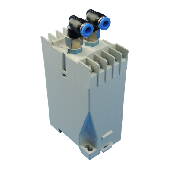
Instruction manual PS11/PK11 Dimension drawings 2x L-Steckverschraubung FESTO elbow (für Schlauch außen-Ø6) (AN) quick connector for PVC tubing (external Ø 6mm) Verschlußstopfen cover seal 7100 003754B_PS11_PK11_eng.doc 02.11.2021 Ze...
Need help?
Do you have a question about the PS11 and is the answer not in the manual?
Questions and answers