Table of Contents
Advertisement
Quick Links
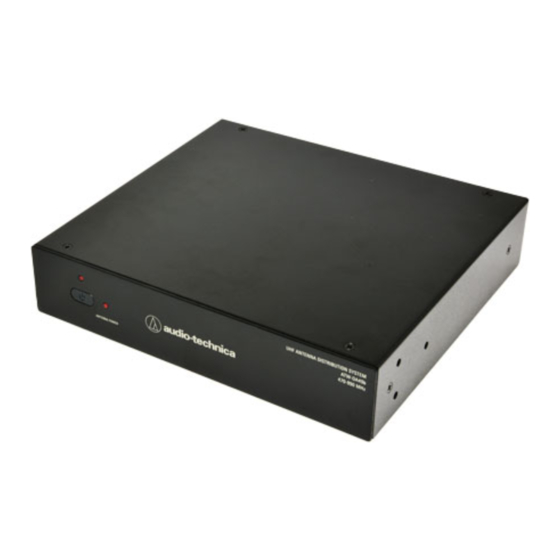
Part names and functions
①
②
①
Power button
Press to turn the power ON/OFF.
An indicator lights up when the power is ON.
②
Antenna power indicator
An indicator lights up while 12V DC supplied
to the antenna input jacks.
③
DC Output jacks
Provides 12V DC (center positive) at up to 500 mA from
each jack to power receivers. Connect the included
DC cables here to supply 12V DC to up to four receivers.
④
Antenna power switch
By turning the antenna power switch ON.
12V DC can be supplied to the antenna input jacks.
⑤
Antenna B output jacks
These are four distribution output jacks of ATW-DA49b
for Channel B.
⑥
Antenna B input jack
Attach the "B" antenna here. The antenna input jack also
provides +12V DC output to power in-line RF devices.
⑦
Antenna A input jack
Attach the "A" antenna here. The antenna input jack also
provides +12V DC output to power in-line RF devices.
Specifications
Frequency range
470 to 990 MHz
Input/output
2 input, 2 × 4 distribution output
Input/output jack
BNC
OIP3
+35dBm (typ.)
RF output gain
+1.0 dB ± 2.0 dB
Input/output gain
+1.0 dB ± 2.0 dB
Antenna input power supply
12 V DC, maximum 250 mA × 2
Power supply
100 to 240 V AC (50/60 Hz) to 12V DC 3.0 A (center positive) switched mode external power supply
Operating temperature range
-5°C to 45°C (23°F to 113°F)
Dimensions
209 mm (8.23")×43.5 mm (1.72")×191 mm (7.52") (W×H×D) (excluding protrusions)
Weight
1.45 kg (3.2 lbs)
Accessories
Rack-mount kit (rack-mount × 2, mounting screw × 6), BNC cable × 10, DC power interconnect cables x 4, AC adapter and cord
For product improvement, the product is subject to modification without notice.
Audio-Technica Corporation
2-46-1 Nishi-naruse, Machida, Tokyo 194-8666, Japan
www.audio-technica.com
©2019 Audio-Technica Corporation
Global Support Contact: www.at-globalsupport.com
③
④
⑤
⑥
⑦
⑧
⑨
⑩
⑧
Antenna A output jacks
These are four distribution output jacks of ATW-DA49b
for Channel A.
⑨
Power input jack
Input jack for the AC adapter.
⑩
AC adapter cord hook
Hang the power cord of the AC adapter to prevent it
from pulling loose accidentally.
⑪
⑫
⑫
⑪
Rack mount kit
The rack-mount hardware kit is provided to permit
attachment in a standard 19" equipment rack.
⑫
BNC bulkhead connectors (optional)
Antennas may be mounted on the front of the long rack ear.
SEP-2020
From No. ATGC-0230-20-WM
ATW-DA49b
User Manual
UHF Antenna Distribution System
UHF ANTENNA DISTRIBUTION SYSTEM
ATW-DA49b
470-990 MHz
Advertisement
Table of Contents

Subscribe to Our Youtube Channel
Related Manuals for Audio Technica ATW-DA49b


Summary of Contents for Audio Technica ATW-DA49b
- Page 1 ⑧ ① Power button Antenna A output jacks User Manual These are four distribution output jacks of ATW-DA49b Press to turn the power ON/OFF. for Channel A. An indicator lights up when the power is ON. UHF Antenna Distribution System ⑨...
- Page 2 • Confirm the frequency band of the connecting wireless receiver, antenna and accessories before use. Although this product was designed to be used safely, failing to use it correctly may result in an accident. To ensure safety, observe all warnings and 2 Antennas cautions while using the product. ATW-DA49b Important information AC adapter Warning: •...
Need help?
Do you have a question about the ATW-DA49b and is the answer not in the manual?
Questions and answers