Table of Contents
Advertisement
Quick Links
Advertisement
Table of Contents

Related Manuals for Uponor KaMo Combi Port Base


Summary of Contents for Uponor KaMo Combi Port Base
- Page 1 Combi Port Base Installation and operation manual CD0000306...
-
Page 2: Table Of Contents
Table of contents Turning off heat interface unit..........23 Setting log heat interface units..........24 Copyright and disclaimer............. 3 Troubleshooting..............25 Preface................... 4 Fault description..............25 Safety instructions..............4 Standards and regulations............4 Correct disposal of this product (Waste Electrical and Technical data.............. -
Page 3: Copyright And Disclaimer
You agree to comply with all copyright laws worldwide in your use of the manual. Modification or use of any of the contents of the manual for any other purpose is a violation of Uponor’s copyright, trademark and other proprietary rights. -
Page 4: Preface
Provide the domestic hot water pipes with required thermal Warning! insulation strength. The Uponor system uses 50 Hz, 230 V AC power. In • Insulate the drinking cold water pipes to secure that no heating case of emergency, immediately disconnect the power. - Page 5 Household users should contact either the retailer where they purchased this product, or their local government office, for details of where and how they can take this item for environmentally safe recycling. Business users should contact their supplier and check the terms and conditions of the purchase contract.
-
Page 6: Combi Port Base System Description
This always ensures a low return Uponor Smatrix or Uponor Base flexiboard. temperatures on the heating water. The energy is supplied by heating water with a flow temperature of at least 55 °C via the heating water Ready to be installed flow. -
Page 7: Components
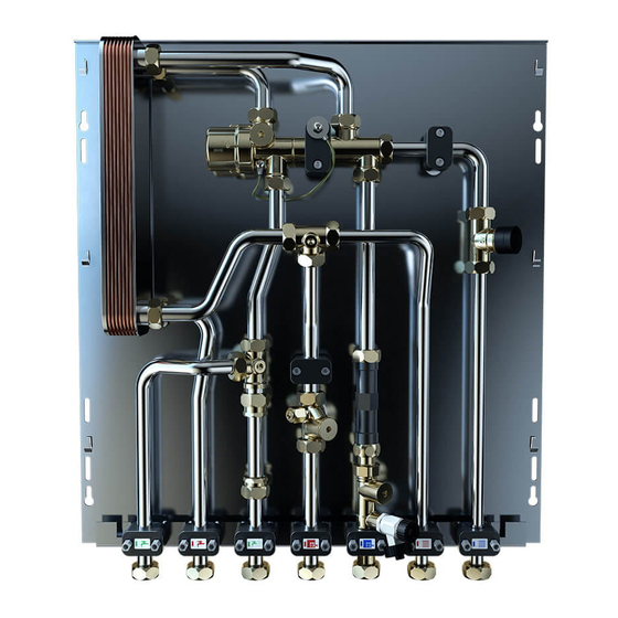
3.3 Components Combi Port Base TWB Note The following illustrations show example set-ups for all units. Individual modules may vary in appearances. Combi Port Base CD0000312 Item Description Proportional volume control (PM) Cold water throttle disc Plate heat exchanger Sensor pocket heat meter Cold water meter distance piece CD0000311 Thermostatic hot water temperature limiter (TWB) -
Page 8: Optional Components
Uponor Smatrix Base PRO Uponor Smatrix Wave Pulse CD0000271 Uponor Smatrix is a fully equipped range of components for room temperature control, optionally via radio or wired. The unique auto- balancing technology eliminates the need for manual balancing of the loops. -
Page 9: Prepare For Installation
4 Prepare for installation 4.1 General information Warning! The fittings are under pressure. Escaping pressurized media can cause serious injury such as scalding or eye damage. Depressurise the system before performing any installation work. For retrofits to an existing system: Drain the system or close the supply lines of the section and depressurise it. -
Page 10: Mechanical Installation
5 Mechanical installation 5.1 In-wall installation Preparations Included parts CD0000240 Item Description Cabinet body Frame Door Dismount the frame and door. Store the frame and door for later mounting. CD0000281 Item Description Adjusting the in-wall cabinet Cabinet body The in-wall cabinets are adjustable inside the niche in height and Coin lock depth. - Page 11 Install the in-wall cabinet Note For freestanding installations, set the height according to the table and adjust the feet accordingly. Pay attention to the horizontal alignment. CD0000243 Item Description Hexagon bolt (4 pcs) Secure the cabinet body to the wall aperture with the enclosed hexagon bolts.
- Page 12 Install the heat interface unit Install the frame and door to the cabinet CD0000245 CD0000247 Item Description Item Description Fixed bolts In-wall cabinet Heat interface unit Frame Hexagon nut (6 pcs) Door Mount the heat interface unit on the fixed bolts in the cabinet Attach the frame to the cabinet body using wing nuts.
-
Page 13: On-Wall Installation
Supporting plate Note See the dimensional drawings for measurements. Pay attention to the horizontal alignment. Attach the on-wall rail to the wall using the hexagon bolts. CD0000284 SI0000277 In-wall cabinet with supporting plate for dry construction. The Item Description supporting plate is mounted from the front and can later be covered with plasterboard. -
Page 14: Installation Of Optional Components
Hang the on-wall frame on to the lateral strips of the base sheet. Bolt in wall cover Mounting plate Attach the mounting plate to the bolts. Screw the nuts onto the bolts. Attach the Uponor Base flexiboard room controller onto the mounting plate with the screws provided. Uponor Smatrix SI0000280 Item... - Page 15 Fasten the distance bolt on the spacers. Additional information Mount the mounting plate using the washers and the screws. Attach the Uponor Base flexiboard room controller onto the Note mounting plate with the screws provided. Visit the Uponor download centre for more information regarding the installation and configuration of Uponor Smatrix and Uponor Base flexiboard.
-
Page 16: Finishing Installation
6 Finishing installation If the fittings are not to be replaced with optional components, replace Warning! the plastic fittings with stainless steel 1.4401 pipes. Contact manufacturer for more information. Leaking connections can cause personal injury and property damages. • Connect the hydraulics correctly. •... -
Page 17: Operation
7 Operation 7.1 Heat meter distance piece 7.3 Strainer Note Caution! The heat meter to be installed must have following Lock the unit and relieve the pressure before any work specifications: Qn = 1.5 1.5-2 seconds. Construction with the strainer. length of 110 mm and ¾"... -
Page 18: Thermostatic Hot Water Temperature Limiter (Twb)
3.2. Reinstall the handwheel to the set value so that it is General information Value blocked with the new setting. Kvs value 1.55 Install the thermostatic tip Max. heating operating pressure 10 bar (PN 10) 4.1. Screw the valve tip on to the valve and the standard Hysteresis +/- 2-3 K setting is changed. -
Page 19: Zone Valve (Av 9)
7.7 Zone valve (AV 9) Pre- setting 0.05 0.09 0.14 0.20 0.26 0.32 0.43 0.57 0.67 Note value / 2 K P It is possible to change the valve setting during deviation operation; the water will not escape. Adjust from default setting to the desired value using a Note hexagonal (SW 13 mm) open-ended spanner, or with a special key. -
Page 20: Heating Pump Settings
7.9 Heating pump settings Pump values Note Variable values Δp-v Please read the installation manual from the pump p/kPa manufacturer. Note In the event of a power outage, all settings and displays are retained. Min. Q/l/s Q/lgpm CD0000256 Item Description RKA = Pump with operating button for Δp-v, Δp-c RKC = Version with operating button for Δp-v, constant speed I, II, III... -
Page 21: Pipe Clip Sensor Safety Temperature Monitor (Stw)
7.10 Pipe clip sensor safety temperature monitor (STW) Before the secondary heating supply is connected, the pipe clip sensor safety temperature monitor (STW) prevents excessive temperatures and provides an emergency-off function for the radiant heating circuit. CD0000258 Item Description Strainer Throttle disc Retaining ring CD0000268... -
Page 22: Filling And Flushing
7.13 Filling and flushing Complete commissioning by following these steps: Check the settings. Complete the acceptance/commissioning protocol. Hand over the documentation and protocol to the homeowner. CD0000265 The filling and draining valve on the heat interface unit is used to fill and flush the system. -
Page 23: Maintenance
8 Maintenance 8.1 General information 8.2 Turning off heat interface unit Ball valves C, D and E must be closed in the event of malfunctions. A visual inspection is required every 3 to 6 months. Important information To ensure the correct and safe operation of the system, this information must be read and followed. -
Page 24: Setting Log Heat Interface Units
8.3 Setting log heat interface units Date: Setting log heat interface units Site: Type: Serial no: Component Description Setting Factory range setting site Set zone valve for Setting value 1 the flow rate continous Kv value / 0.05 0.09 0.14 0.20 0.26 0.32... -
Page 25: Troubleshooting
9 Troubleshooting 9.1 Fault description Fault description Cause Solution Hot water function Hot water temperature too low or Central heating fluctuating Buffer temperature too low Buffer temperature must be 5-10 K above hot water setpoint Heating circuit pump type not The following pump type is supported: Wilo Stratos supported Setting for heating circuit pump is... - Page 26 Fault description Cause Solution Air in the system Vent the system Radiator supply Zone valve flow too low / too high Check the Kv value on the zone valve Setting for room temperature Check the setting for the room temperature controller controller is not correct Strainer is dirty Clean the strainer...
-
Page 27: Technical Data
Strainer Safety temperature limiter Heat meter distance piece Plug n' play connection (oil cable 3 x 1 mm²) Sensor pocket heat meter Uponor Base flexiboard Valve Room temperature control Zone valve for limiting heating flow to apartment Component side cable... -
Page 28: Dimensional Drawings
10.2 Dimensional drawings All dimensions are given in mm. In-wall cabinet with distributor Combi Port Base ZD0000026 555.5 82.75 1240 1190 1189.5 22.35 Combi Port Base TWB In-wall cabinet 555.5 82.75 ZD0000025 1090 23.35 Combi Port Base Installation and operation manual... -
Page 29: Hydraulic Schemes
In-wall distribution cabinet Item Description Proportional volume control (PM) Cold water throttle disc Plate heat exchanger Sensor pocket heat meter Valve Equipotential bonding connection Earthing on site Zone valve for limiting heating flow to apartment Heat meter distance piece Strainer Draining and filling valve Connection, ball valve Combi Port Base TWB... -
Page 30: Performance Curves
10.4 Performance curves Pressure losses at the throttle disc must be included in the calculation. • 10 l/min = 0.65 - 0.85 bar Pressure losses with 24 plates • 12 l/min = 0.68 - 0.88 bar • 15 l/min = 0.70 - 0.90 bar •... - Page 31 Cold water warming 40 K (10-50 °C) Pressure losses with 40 plates 55 °C 60 °C 65 °C Heating side (primary) 1200 70 °C 1100 75 °C 1000 80 °C 0.80 85 °C 0.70 0.60 0.50 0.40 0.30 0.20 Item Description 0.10 Primary heating demand in litres/hour (l/h)
- Page 32 • 10 l/min = 0.65 - 0.85 bar Cold water warming 40 K (10-50 °C) • 12 l/min = 0.68 - 0.88 bar • 15 l/min = 0.70 - 0.90 bar 55 °C 60 °C 65 °C 1200 • 17 l/min = 0.75 - 0.95 bar 70 °C 1100 •...
- Page 33 Combi Port Base Installation and operation manual...
- Page 34 Combi Port Base Installation and operation manual...
- Page 35 Combi Port Base Installation and operation manual...
- Page 36 Industriestraße 56, D-89584 Ehingen, Germany D-97437 Hassfurt, Germany 1095280 v1_03_2020 Production: Uponor/ELO/SEM Uponor reserves the right to make changes, without prior notification, to the specification of incorporated components in line with its policy of continuous www.uponor.com www.kamo.de improvement and development.
Need help?
Do you have a question about the KaMo Combi Port Base and is the answer not in the manual?
Questions and answers